< Brake System 4 >
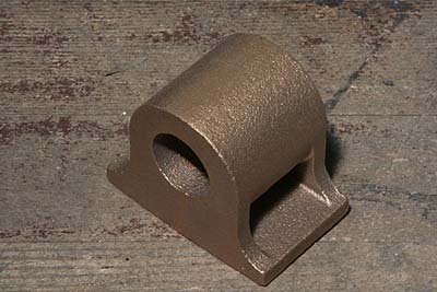
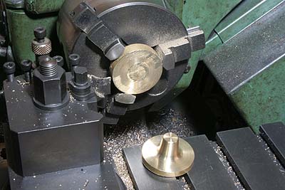
The brake cylinder is made of gunmetal casting
ordered with a pattern by MODELA.
After cleaning the bottom face, the bore
is finished in a desired diameter on the
face plate. At once, a section for cylinder
cover is finished. After that, the casting
is reversed and another section is finished.
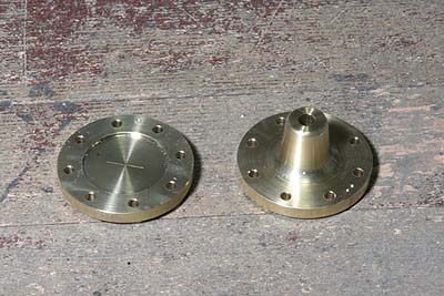
The cylinder covers are made from brass round
bar. The under cover has projection supporting
the piston rod.
To save material and cutting effort, the
under cover blank is silver soldered from
different brass rods. Projection profile
is turned and parted off without center hole.
The center hole is drilled and reamed when
the inner fit is finished.
![]()
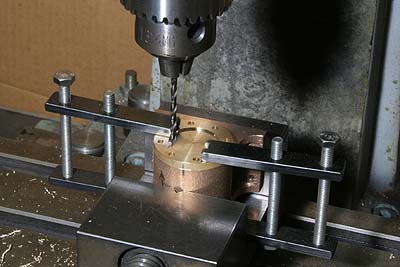
Bolting holes are positioned by X-Y stage
of the milling machine. The drill goes through
the cover and countersinks the body. After
that the cover is removed and the body is
drilled and tapped.
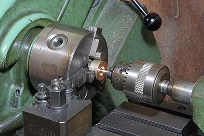
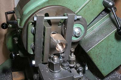
The piston is made from gunmetal round bar,
and the piston rod is made of free-cutting
stainless steel bar. The rod is press fit
into the piston. The top half of the fit
is threaded so as to pull the rod into the
piston. The photo shows pulling the rod by
rotating the head by hand.
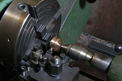
After the press fit, the piston is finished
to a desired diameter. The rod is exactly
centered in four-jaw with a dial gauge. Finally
a groove for O-ring is cut.
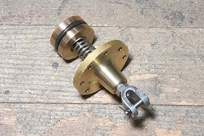
A coil spring is inserted between the piston
and the under cover, and a cross head is
screwed into the piston rod. The crosshead
is bent from a steel bar and secured by a
lock nut. The O-ring pressure should be enough
small to allow the piston move by the coil
spring. The coil spring is made from 0.9mm
stainless steel hard wire. The coil's O.D.
is 10mm.
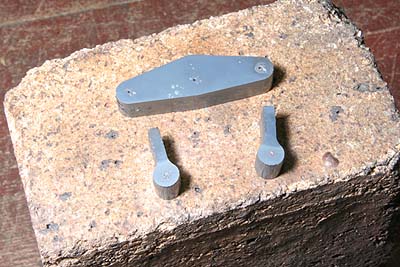
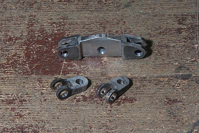
The parts to connect the crosshead to the
brake arms are made from laser-cut thick
plates. The center hole of the equalizing
arm is cut tapered from both sides.
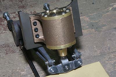
The photo shows assembled brake cylinder
with the brake arms. The cylinder is mounted
onto one of the chassis stretcher. Steam
inlet will be prepared at the side of the
cylinder. Right now I cannot optimize the
inlet because I have not finished design
of the boiler.
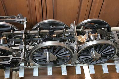
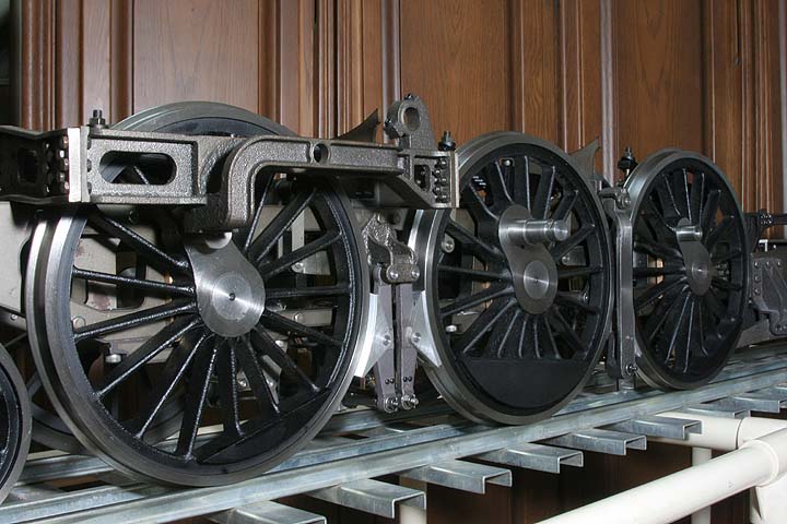
The brake system is attached into the chassis.
In the photo the chassis is on a sharp bend
track of 7.5 meter radius. The brake shoes
follow the curve very well but I found the
second brake shoes tend to drop out from
the wheel frange.
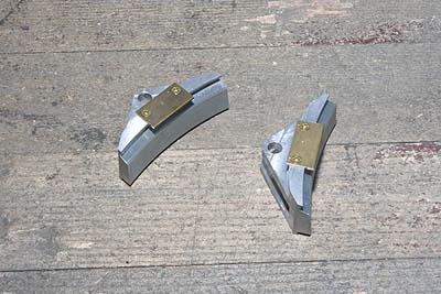
I had no choice but add support plates on
the back faces of the brake shoes. They hold
the wheel franges firmly.
The whole brake system is completed.