< Cylinder Block Cutting 1 >
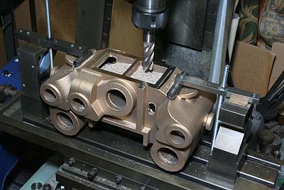
I started cutting of the cylinder block.
At first, top reference surface is cut by
milling machine. Before clamping, I adjusted
packing at four corners to hold the casting
truly horizontal.
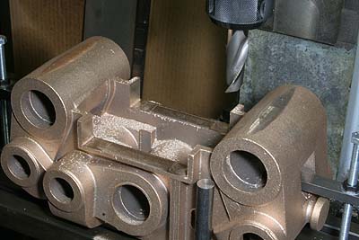
The job is reversed and three faces of the
bottom channel are cut. Side faces of the
channel become side reference. Note a steel
round bar standing near the right cylinder,
that is as a gauge to finish the top face
in desired height from the milling stage.
Here I also cleaned bottoms of the outside
cylinders.
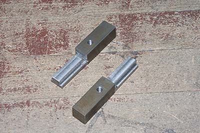
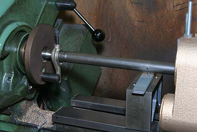
I will mount the casting on the lathe table
and finish cylinders and valve chest bores
with boring bar. But the casting is too wide
to clamp onto the Myford S7's narrow table
in the usual manner. So I made T-slot extension
nuts as shown in the photo. Some weakness
cannot be avoided.
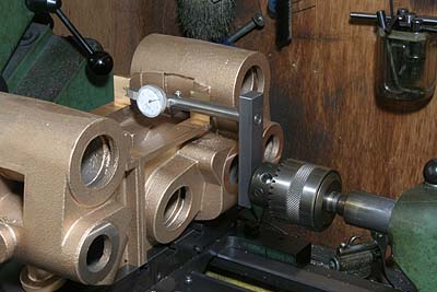
Reversed and mounted on the table, the valve
chest center is coincide with the lathe center
in height. Then the valve chest is aligned
truly parallel to the lathe bed with DTI
in the tailstock.
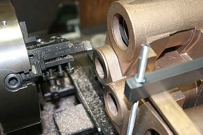
First, valve chest cover bolting faces are
finished with a fly cutting tool, that is
just a knife tool in the tool post gripped
by four-jaw.
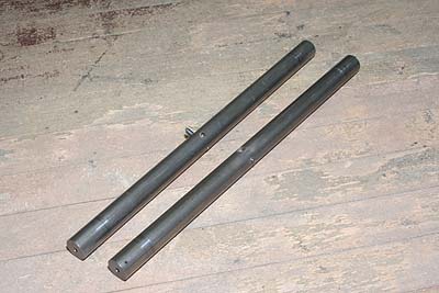
The boring bars are prepared from 20mm silver
steel rods. At the middle of the rod, a boring
tool is hold in a cross hole and secured
by set screw. Both ends of the bar are center-drilled.
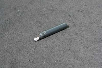
Thin boring tool for valve chests is made
from 5mm HSS drill.
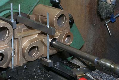
After removing unwanted walls in the valve
chest by a hole saw (refer the last month
report), I started boring. The bore diameter
is expanded from 25mm to 33mm with 0.4mm
steps.
The tool diameter is adjusted with suitable
block and plates between the tool and lathe
bed.
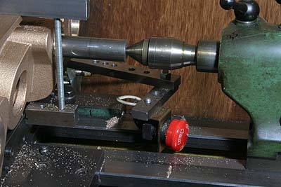
As usual, I employed limit switch to stop
the lathe motion at the end position.