< Steam Chest Cover 2 >
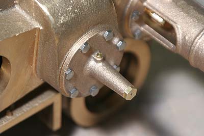
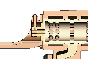 The picture shows section of a steam chest
gland. Full size steam chest is pressure-sealed
but my model's isn't. The steam chest cover
is centered toward the steam chest by the
gland. Also the glands push the piston liners
from both ends.
The picture shows section of a steam chest
gland. Full size steam chest is pressure-sealed
but my model's isn't. The steam chest cover
is centered toward the steam chest by the
gland. Also the glands push the piston liners
from both ends.
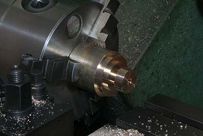
The glands are made from gunmetal round bar.
After all of turning and boring operation,
the work is parted off, reversed and finished
to a desired length. At this point, the front
glands are kept 0.2mm longer than final length.
As the upper picture shows, the center hole
is a little enlarged from bottom side because
too long bush causes friction even with a
small error.
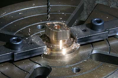
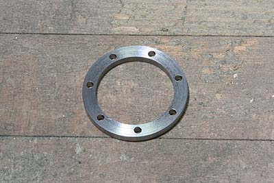
Full size gland is sealed by diamond shaped
flange. The diamond shape is milled with
rotary table. Holes for dummy bolts are also
opened here.
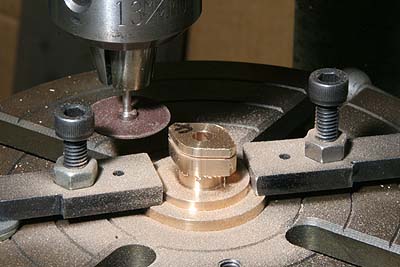
Dummy parting line between the flange and
the gland is cut with a sanding wheel.
This is drilling jig for the covers, turned
from a steel round bar blank. Cross lines
for alignment are scribed on a face and the
side.
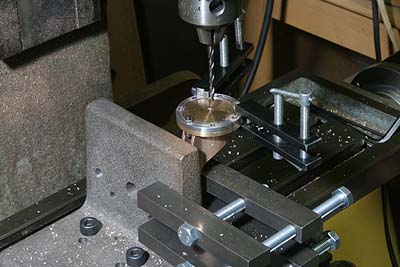
The front cover has a horizontal groove in
its bottom. One of secure bolts has to be
in the groove. So I drilled larger hole for
the bolt, then fixed the jig onto a cover
with a bolt, and drilled other holes through
the jig.
The back cover holes are simply drilled through
the jig at a time.
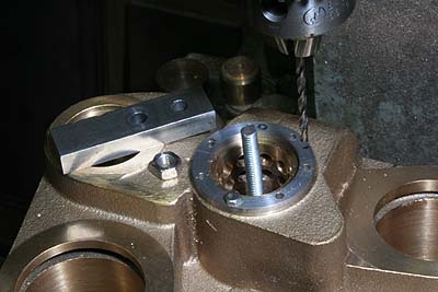
The cylinder block is countersunk through
the jig, drilled undersize and tapped. Probably
clamping hides some holes of the jig. Firstly
open two holes and fix the jig by screws,
then open the rest of holes.
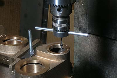
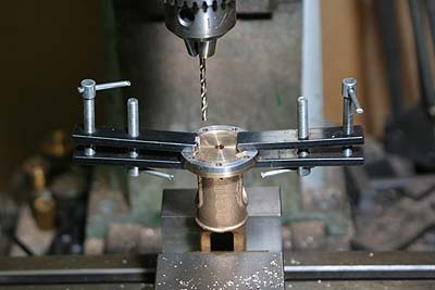
This is my method to tap holes. After drilling,
keeping the position, replace the drill with
a smaller drill-chuck with tap and handle.
And then slightly slacken the larger chuck
so as to let the smaller chuck move freely
for tapping. Note a nut in the tap to indicate
depth of the hole.
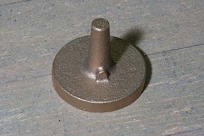
This is a gunmetal casting for back cover
of the inner steam chest.
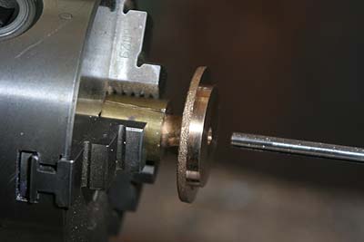
In order to chuck tapered bush truly, I prepared
simple brass collet that has tapered bore
and a side gap.
The back cover is bolted onto the cylinder
block. Oil cup plug and bush end plug were
screwed into the cover. Note a vent hole
of the bush end plug.
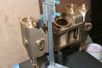
Here the 0.2mm longer front glands are finished
as follows. All of parts except the front
cover are assembled to the cylinder block.
Height difference between the front gland
and the cylinder block bolting face is measured
by height gauge. Finally, each front gland
is finished as the difference becomes 0.05mm.
This value holds the liner firmly in the
steam chest with a minimum distortion of
the cylinder block.
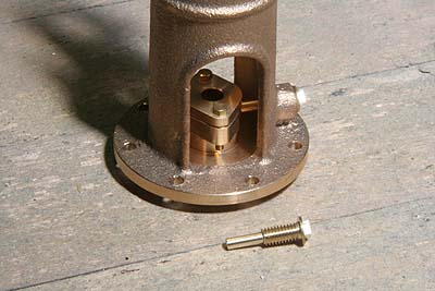
The cover and the gland have to be connected
by an oil pipe. I extended oil cup plug to
imitate the oil pipe. This long bolt also
prevents the gland from rotating.
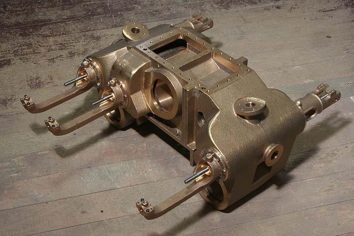
All of the steam chest parts are assembled.
Each valve spindle should rotate freely.
Any tightness shows centering error of the
glands.