< Main Cylinder 1 >
Next I tackled with the cylinder covers.
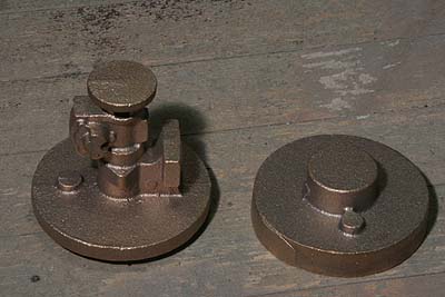
The photo shows castings of them. Front cover
casting has spigot to chuck in three-jaw.
Back cover casting is unified with another
component 'tail rod box', which will be cut
off from the casting. All covers have eccentric
bosses to catch cylinder safety valves.
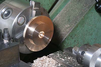
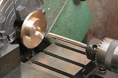
I started with the front covers. Chucked
with a spigot, side and inside faces are
cut and finished. The center recess is a
clearance for piston secure nut.
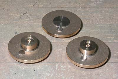
After that the spigots and eccentric bosses
are turned off. Note two of them (for outer
cylinders) have center projections as bolting
faces for the tail rod boxes. Prototype's
piston rod is designed to go through front
cover and held by a tail rod box. I have
no intention to reproduce it but I will make
dummy tail rod boxes.
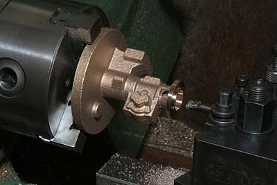
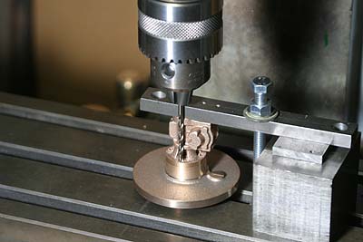
Next is the tail rod box. Chucking the back
cover part, foot side of the tail rod box
is machined.
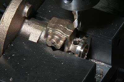
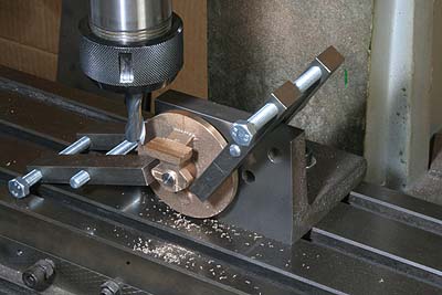
Side windows of the tail rod box are opened
by end mill. Later, they will be finished
triangular by thin round file.
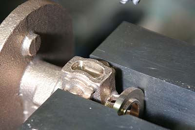
After some additional cuts for detailing,
the tail rod box part is sawn off.
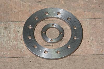
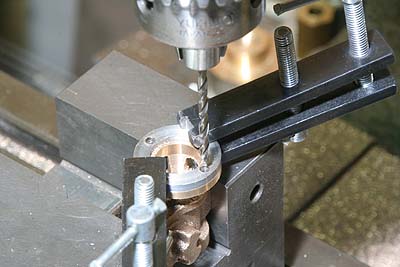
Here I prepared drilling jig for the tail
rod box. The inner one is it and the outer
one is drilling jig for the cylinder covers.
Both of them are made from steel round bars.
The tail rod box is drilled through the jig,
then the front cover is drilled through the
box.
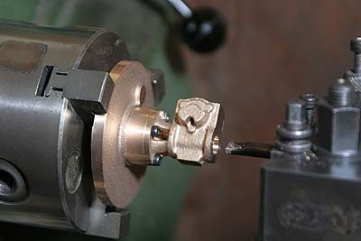
The tail rod box is bolted onto the front
cover. Chucking the front cover part, opposite
end of the box is machined.
A small bush for tail rod case is bolted
on front face of the box. The bush is turned
from a brass round bar. Other small screws
are added for detailing.
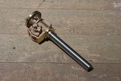
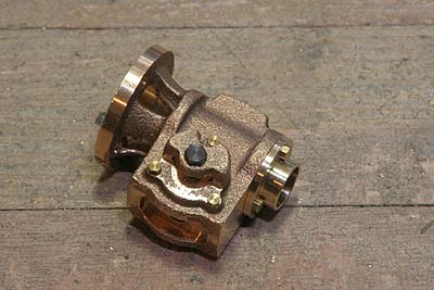
The tail rod case is made from a steel bar.
The full size tail rod (front end of the
piston rod) itself can be seen through a
window in the box. In the model, the tail
rod case goes through the box and its back
end is turned down to the tail rod's diameter
to imitate it. The tail rod case with dummy
tail rod is secured with a set screw in the
box from underneath.
Finally the cylinder back cover is machined.
Inside face is cut in the same manner as
the front cover, but the center hole for
piston rod is drilled and reamed.
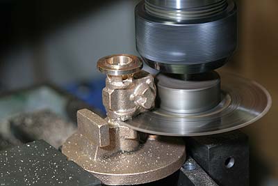
The slide bar bolting face should be finished
truly parallel to the center hole and in
desired height from the center. I prepared
a jig with angle plate and round bar. After
roughing cuts, the end mill is adjusted to
a final height. Then all of three back covers
are finished in the same height.
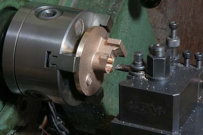
Again back cover is chucked in the lathe.
Cavity for gland is opened with a boring
tool. I intend to use O-ring for sealing.