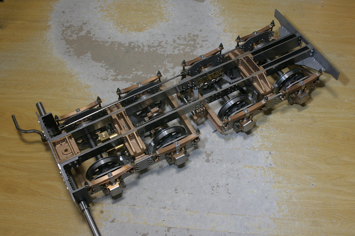
< Completed Tender Chassis >
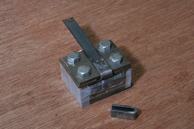
As always, the fork plates of brake rods are made from band plate by the bending jig. I utilized 8 mm and 10 mm width with 2 mm thickness plates. After annealing, bend once to L-shape, then bend to U-shape in the jig.
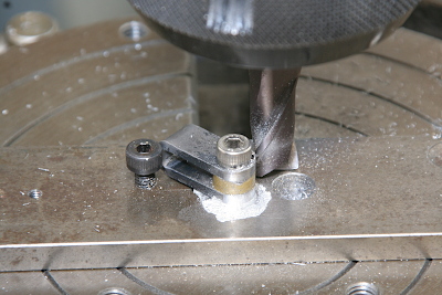
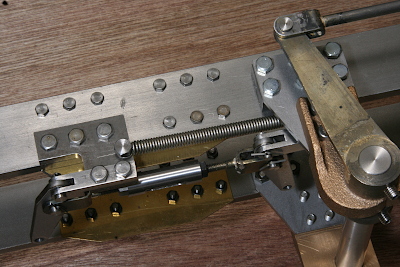
Tip of the fork plate is rounded in the rotary table. Open the center hole in advance, secure the hole to table center with a screw and cut by end mill. Note anther support screw that prevents dragging of the job around the center screw.
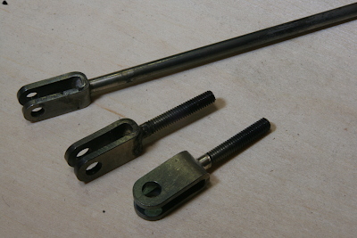
Finished fork plates are silver soldered to round bar rods. In addition to usual brake rod with two forks at both ends, I need two rods with a forked end and screwed end in each. They are for an adjusting sleeve (see below) and have M4 normal and M4 reversed screws. I utilized usual and reversed dies.
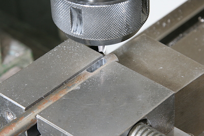
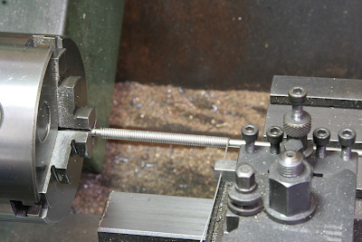
The adjusting sleeve is 10 mm dia. short round bar with M4 normal and reversed screw holes at both ends. In order to open different screw holes from both ends, cut a slot in the middle part. That is cut by end mill before cutting the rod to desired length.
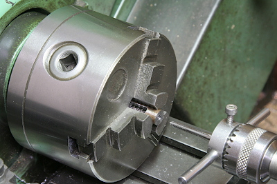
The sleeve is screwed in the lathe. I utilized usual and reversed taps, too.
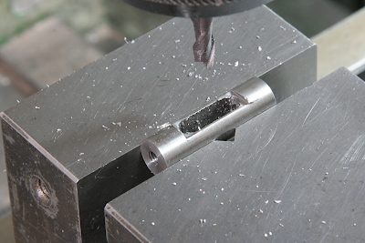
Area around the slot is cut to 8 mm thickness so as to be held by a wrench.
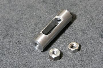
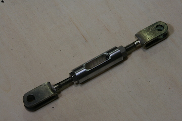
The left hand photo shows finished sleeve and lock nuts. The right side nut is a commercial nut, while the left side one is a home made reversed nut. The right hand picture shows the sleeve with a pair of forks. Loosen the nuts and rotate only the sleeve, then the link length changes.
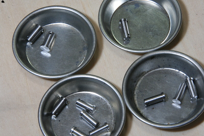
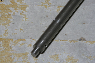
These are link pins turned from a stainless steel bar. Each has a cross hole for a split pin.
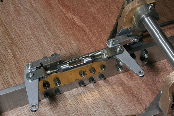
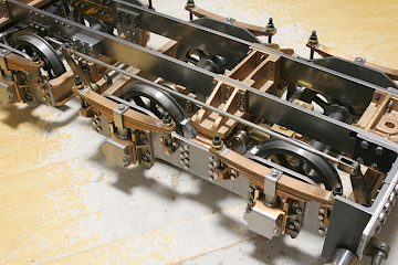
The sleeve is connected to laser-cut link plates. The bottom holes of the link plates are linked two bogie brake beams. One of the top holes is held in the link bracket under the chassis. And the other is linked to the brake pedal.
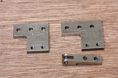
Position of the link bracket was calculated from full size tender drawings. But it was not suitable for total balance of the brake links. So I changed the bracket position a little. The photo shows baseplates of the bracket before (left) and after(right) modification. Note position of holes for screws are a little shifted.
When the brake is released, the brake pedal is pulled back by a coil spring. I wound the coil spring in the lathe. I designed it can pull by 10 Newton force and wound 0.9 mm stainless spring wire to 6 mm O.D. coil. It is tension spring, so it is wound closely.
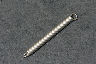
Finished coil. The rings at both ends are raised so as to fix to something.
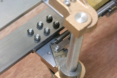
The front end of the spring is hooked to a top hole of the short arm on the middle brake axle. The arm has another hole connected to the link plate through the free link that was made three months before.
The back end of the spring is fixed onto the link bracket's baseplate.
The front and middle brake axles are synchronized through two arms and a forked rod. After adjusting, small recesses for set screws are drilled on the front axle likewise for the middle axle.
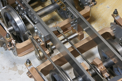
The long and short arms in the middle axle strengthen the braking force due to radius ratio of the arms.
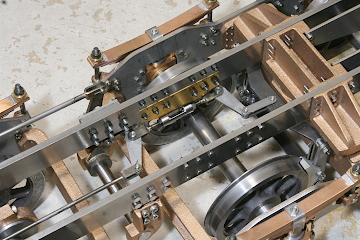
Tender chassis was completed. For a test run, the wheels should be painted and glued onto the axles.