< Silver Soldering Operations #4 >
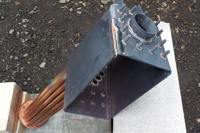
The forth series of silver soldering operations start with the inner firebox recovery. As the solder should flow in both sides of the thin plate, the solder wire pieces are lined up along both sides of the plate.
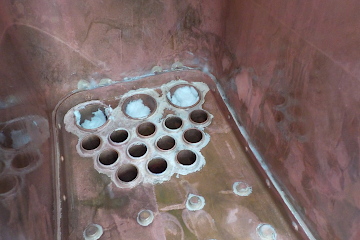
Regarding the inner tube plate, I never found any light leakage at the test, but it looks the solder amount is too small to cover whole width of the flange. Therefore I added some flows of solder here. Note the outer and the inner of the tubes and flues are protected by ceramic sheets.
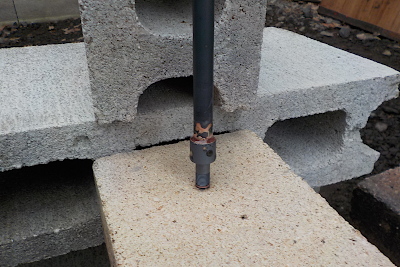
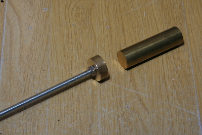
A nozzle is soldered at an end of the hollow stay copper tube. The nozzle is made from a gunmetal round bar. After that, longitudinal stays and the hollow stay will soldered onto the backhead (no picture).
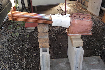
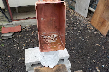
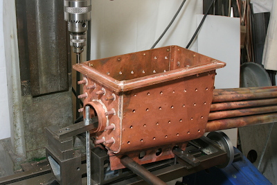
Next is soldering the foundation ring. As the photo shows, ceiling of the inner firebox is held by a stood brick and the foundation ring touch nothing. The front of the tubes are raised up so that the foundation ring top face becomes horizontal. The root of the tubes and flues are protected by a ceramic sheet.
Start with a point of the foundation ring and go around the ring confirming that the placed solder pieces are melt and flow out to the bottom face of the ring. It takes about ten minutes in total.
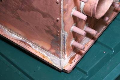
The photo shows view after pickling. Note small thin plates are inserted between the side parts and the back part of the foundation ring in order to eliminate small gaps.
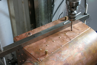
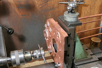
From here I started home work again. The last item of the boiler parts, namely side stays are installed in the firebox. The boiler is fixed on the stage, drill and tap through the inner and the outer fireboxes, and screw the side stays into the fireboxes. First the diagonal two points are fixed by long studs so as to fix the inner and the outer firebox each other, after that the rest positions are fixed by the side stays.
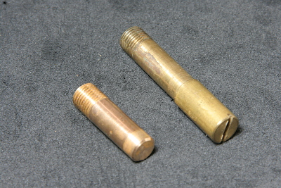
The phosphor bronze side stay's body is 7 mm dia., the thread is M7.5 x 0.75 mm, and has 6.9 mm dia. step at top. The studs for diagonal points are turned from 8 mm brass rod to 7 mm step and threaded.
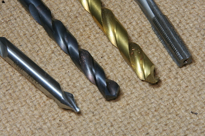
The photo shows tools for the operation. The procedure is as follows. Start with a center drill, drill through a 6.5 mm drill, widen only the outer plate by a 7.1 mm drill, thread the inner plate by M7 x 0.75 mm tap, and screw a side stay into the both plates. The 6.5 mm drill is 'web thinning' drill that can be used without center punch, in order to eliminate deviation at start drilling the inner plate.
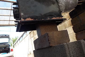
The magenta parts in the drawings show boiler shoes at four corners of the foundation ring. They reform the tilt foundation ring partially to horizontal, in order to eliminate up and down movement of the boiler by thermal expansion.
The screw holes to fix the boiler shoes are opened on the foundation ring. the holes are blind so as to cancel leakage risk, even though the shoes will be finally soldered onto the ring.
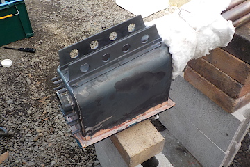
Drill and tap screw holes on the backhead to fix the fire hole door assembly. These are also blind holes. The screw positions are thickened to 6 mm by soldered backing plates. The holes will be filled with plaster before soldering so as to prevent solder leakage.
This is a pair of hand made tool in order to pack ceramic sheet into the tubes, hard and without gaps.
All of the machining process for the boiler is finished. All that remains is the final soldering operation.