< Regulator Valve 2 >
 The regulator valve is operated by a lever on the backhead. The lever is
pulled by a coil spring in order to against the boiler working pressure.
The lever has a latch to keep the lever in the desired position.
The regulator valve is operated by a lever on the backhead. The lever is
pulled by a coil spring in order to against the boiler working pressure.
The lever has a latch to keep the lever in the desired position.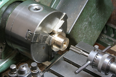
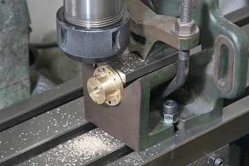
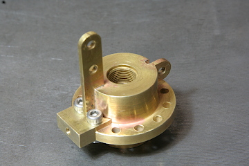
The regulator gland is turned from a brass round bar. Cut a room for an O-ring and tap threads for a gland nut.
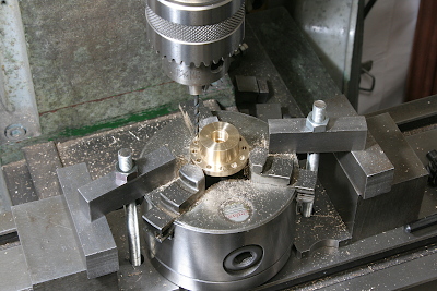
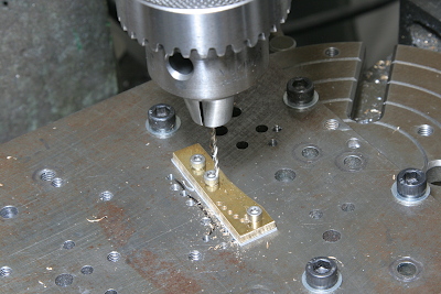
Set the job on the milling table together with the three-jaw. Drill holes by the x-y coordinates.
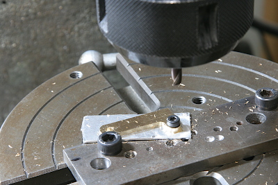
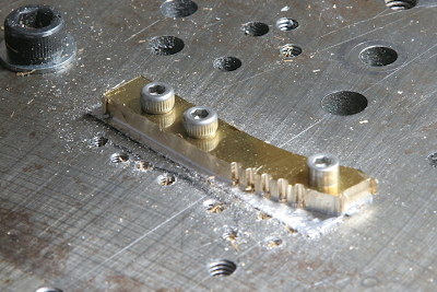
The brackets to hold some parts are made from a brass sheet. They are milled on the rotary table.
Mill grooves in the gland and the brackets are silver soldered.
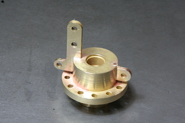
After that, I designed the coil spring and understood that the capacity for the coil spring is too short. So I made a new bracket on the side of the flange and sawed off a part of the bracket. The fixing screws will be screwed into the regulator bush.
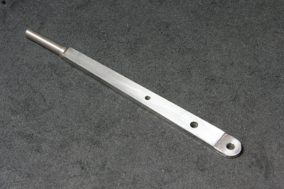
The main lever is laser-cut from a stainless steel sheet. The round part at the top is turned from a round bar and silver soldered to the lever body.
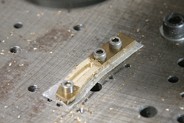
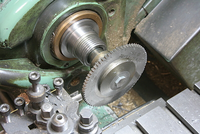
The arc plates with notches are made from brass sheets. First, drill small holes for the notches.
Cut inner and outer curbed edges, and then the notches appear. Each notch is corrected by an end mill of the same diameter as the drill.
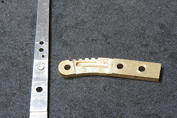
In order to against the pressing force of the latch, one of the arc plates has a curved groove on the inside face, and a pin through the main lever traces the groove. The curve is calculated by the CAD. The curve and the outer shape of the arc plate are not concentric, because the angle of the lever changes due to its position.
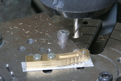
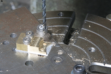
The tips of the arc plates are also finished in the rotary table. The plate under the job is a jig plate utilized many times.
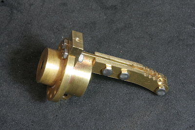
The arc plates are fixed on the gland. They are held with a gap between each other by the bracket and a ring on the tips.
A crosshead for the main lever is screwed into the stem end. The slit of the crosshead is cut by a metal saw.
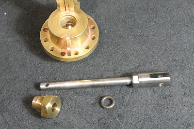
The stem is sealed with an O-ring and closed by the gland nut. The working range of the slide valve is adjusted by the crosshead position and fixed by a lock nut.
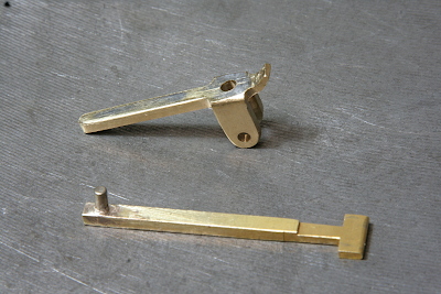
The latch plate and the sub lever are made from a brass bar. Formed by an endmill and files. The latch has a 'T' shape and the bottom 'T' is inserted in the notches. A stainless steel pin is silver soldered on its top and the pin is in a hole of the sub lever. Then the sub lever drives the latch plate.
The latch plate is held on the main lever with a brass bracket, that is fixed on the lever with two screws.
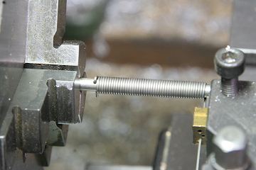
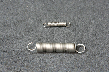
The two kinds of coil springs are coiled from 0.7 mm dia. and 0.4 mm dia. cold-drawn stainless steel wires.
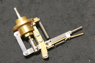
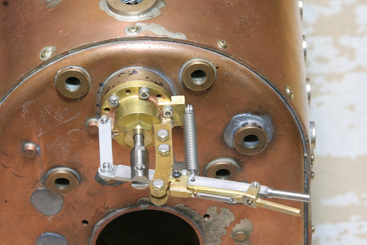
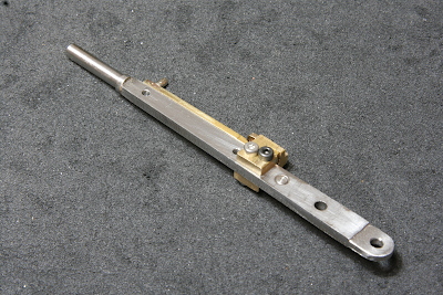
The assembled regulator lever. Each pin is a stainless steel round bar fixed with E-rings. The force of the coil spring is balanced to the boiler working pressure at the full closed position.
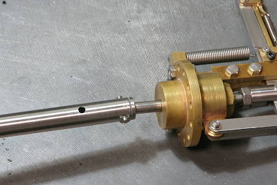
The reach rod to the steam dome is a stainless steel pipe. A stainless steel bush is silver soldered at the back end of the reach rod. The stem is connected to the bush with a cross pin. The cross pin is held horizontally and the reach rod could slightly tilt.
The photo shows the regulator lever assembly mounted on the backhead.