< Boiler Cleadings 1 >
As the diameter of the boiler is comparatively smaller than that of the prototype, there is a large space between the boiler and the cleadings. In order to hold the cleadings, aluminum rings and domes are set on the boiler at regular intervals. The rings are divided into the left and right half rings.
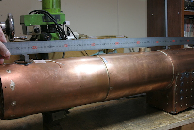
The completed boiler has a large deformation also in the barrel, concretely the barrel section became flat. In order to design the rings, the actual shape of the boiler should be clear. A meter rule, as a straight edge, and a large caliper are utilized to measure the deviations from the design, and I got the whole actual shape.
The drawings show the measuring result. The gray lines show the original design and the magenta lines show actual shapes. As well as the barrel section becoming flat, the bottom end of the barrel is dented upwards. I will adjust the aluminum rings' shape in order to make the cleadings' section circle as true as possible.
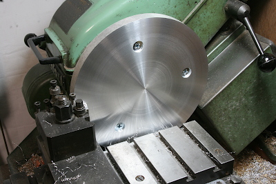
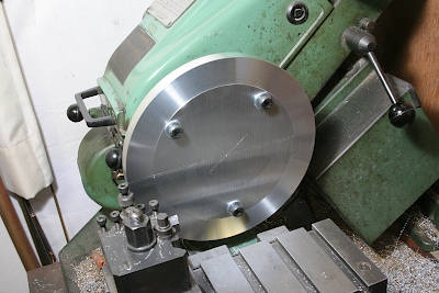
The aluminum rings are made from aluminum alloy discs sliced from a large round bar. Their diameter is almost the same as the driving wheel's diameter. The flatness of the disc surface is not good, so I started turning with truing up the surface. The disc is fixed on the faceplate by three countersunk screws with washers in order to float the disc from the faceplate.
Reverse and finish the backside. Only the outer area is finished because the inner area is not in use. Here the outer diameter of the disc is temporarily finished.
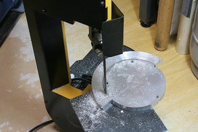
Cut out the half rings with a band saw. Here the internal stress of the material is released and the ring's shape deforms.
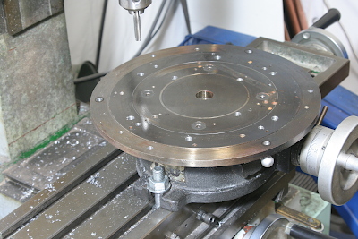
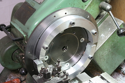
The subsequent processes are done with a large disc plate utilized for the driving wheel turning. The photo shows drilling and tapping fixture holes on the disc plate. Note the disc plate already has a number of fixture holes for many past purposes.
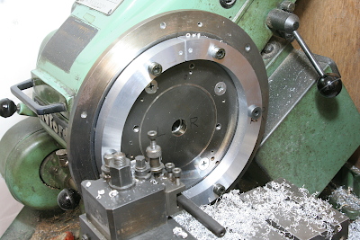
Fix the disc plate on the faceplate, fix the half rings on the disc plate, and finish the inner and outer diameters of the half rings.
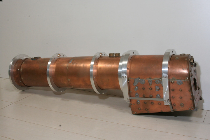
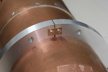
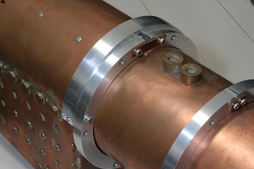
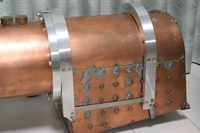
The half rings are fixed on the boiler barrel as the photos show. A pair of band plates connect the top joint, while a crosswise bolt directly squeezes the bottom joint. As the barrel section is flatly deformed, a copper sim is inserted in the bottom joint, which is secured on the ring with an invisible small pin.
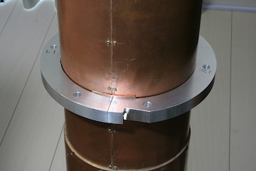
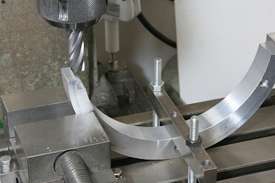
For the firebox, only upper half rings as domes are necessary. As the outer and inner circles aren't coaxial, they could not be turned at a time. Moreover, the firebox roof is also flatly deformed, the inner circle should be finished as half of a horizontally long circle. The long circle could be formed by shifting the job's center in a side direction. The upper and lower half rings in the photo are for the first and second domes on the firebox. Their inner half circles are once turned, reversed, and turned again. Finally, they are finished in long circle shapes.
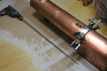
The first dome on the firebox is contacted and bolted onto the last ring on the barrel. In order to drill the support through the last ring, the electric drill shank is expanded with a steel round rod to clear the barrel.
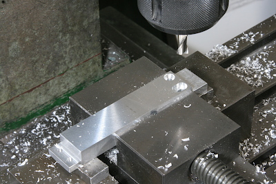
Both bottom ends of the domes are cut in steps in order to fix aluminum columns that cover the firebox's lower part. In order to fix the job on the milling table, I utilized both the vise and a clamp.
The columns are made from the inner excess part of the aluminum disks. Cut steps for assembly in both ends.
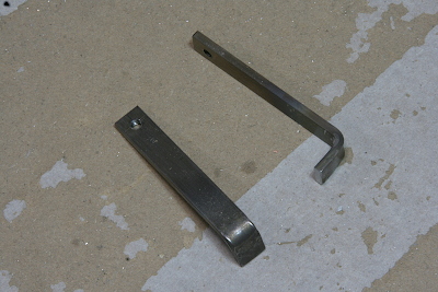
As the second dome could not be fixed on anything, Fix hooks at the bottoms of both columns that hook the firebox foundation ring. The hooks are made from a steel band plate.
The photo shows the assembly of the domes around the firebox. The first and second columns are connected with band plates at their bottoms. Note the holes on the columns to fix the hooks are long circles. The hooks are pulled hard and fixed by the screws.
The boiler is ready to catch the cleadings. However, before it, I will prepare a dummy firebox and mount it around the actual firebox.