< Tender Body 2 >
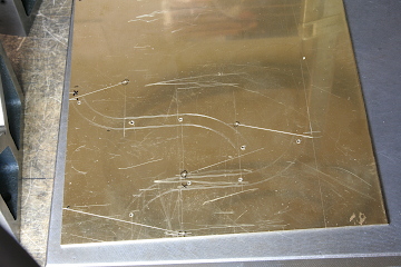
The upper rim of the tank is enclosed by band plates, each measuring 6 mm in width and 1.2 mm in thickness. These band plates are prepared by cutting them out from a larger sheet of material. The curved front and rear sections are individually scribed and cut. Note the holes for rivets were pre-drilled before the cutting process.
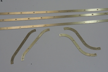
Brass angles, needed for the assembly, have been cut to the desired length, and rivet holes have been drilled into them.
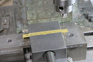
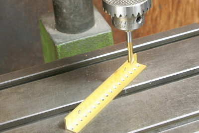
The back sides of these holes have been countersunk to facilitate riveting.
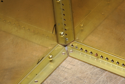
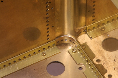
The tank is temporarily assembled using these brass angles, secured in place with M1.7 screws and nuts. In the photo, you can see the bottom corner of the tank with three of these angles in position. Note the end of each angle has a diagonal edge.
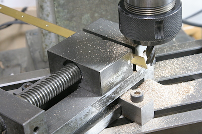
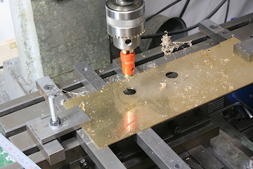
These diagonal edges were cut by an endmill in a vice set at an angle.
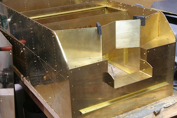
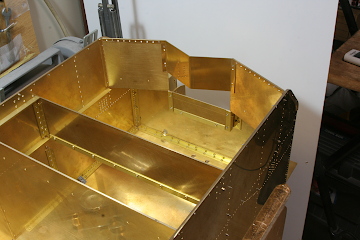
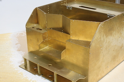
The front section of the tank features a complex structure. I've replicated it using 1.2 mm thick plates, which have been assembled with brass angles. Although the original prototype had a sloped top (coal bank bottom), I've opted for a flat top design to prevent water from infiltrating the coal bank.
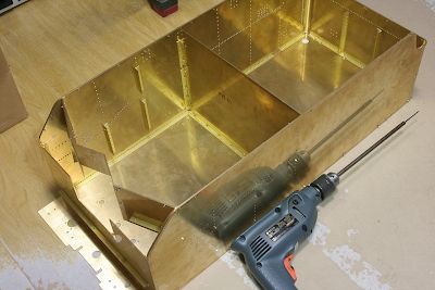
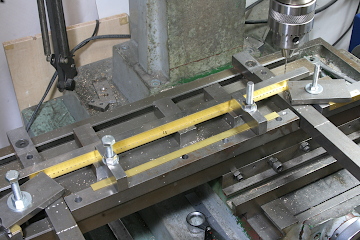
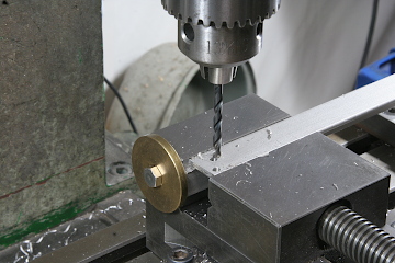
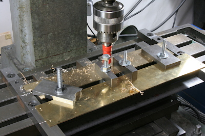
After assembling the body, it's mounted onto the bottom plate. Then, the bottom plate is countersunk through the holes in the brass angles along the inner side of the body. Following this, the bottom plate is drilled and tapped. Note an extended drill bit is employed to ensure clearance for the drill head.
The rounded corners of the back plate are lined with circular plates to increase the soldering section area.
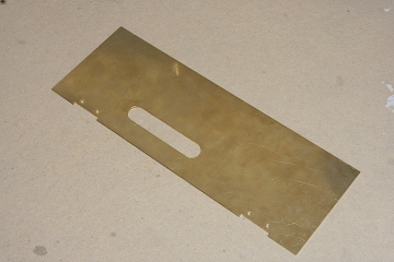
Between the coal bank and the driver's seat, there is a top panel. This panel features a slotted hole to accommodate the hand pump's lever. Create two circular holes using a hole saw and connect them using a fretsaw.
For supporting the driver's seat, I've fashioned a frame from stainless steel angles, employing a drill suitable for stainless steel. The angles are trued up using an endmill.
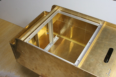
The frame is then installed beneath the driver's seat. The top horizontal beams are secured by columns positioned directly on the chassis frame via the tank's bottom plate. The longitudinal beams serve for structural stability. Note the bottom horizontal beams are relatively short to ensure effective drainage.
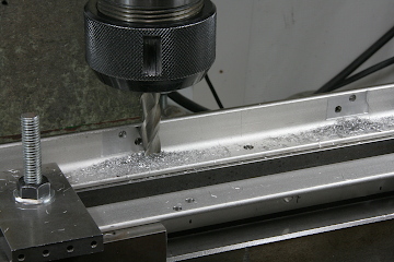
The front deck is constructed from a 2 mm thick brass plate. The photo shows creating a hole for the drawbar pin.
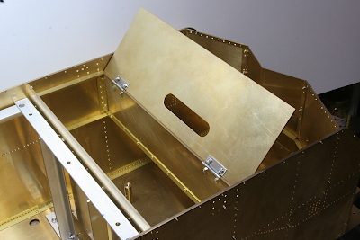
The top panel can be opened and closed using stainless steel hinges. This access point can be used to fill the tank with water.
The front deck is supported by brass square bars. The round and slotted holes on the shoulder are designed for the axle-driven pump's bypass valve.
At this stage, the tender body assembling was completed temporarily.
