< Tender Body 3 >
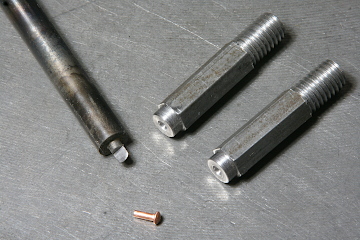
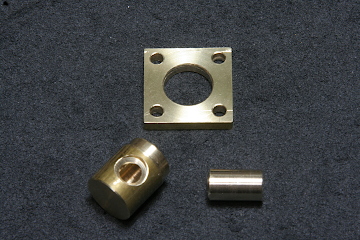
When riveting the water tank wall, a dolly to secure the copper rivet head is necessary. I fabricated a cutter to shape the dolly's concave. The photo shows the cutter and the dolly. Both were hardened and tempered. The dolly has a threaded bottom in order to be fixed on a work stage.
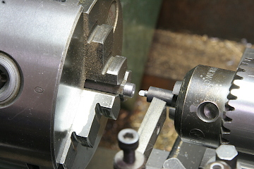
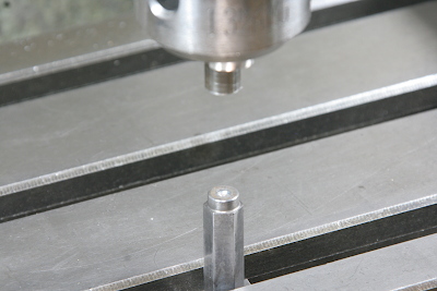
The rivets are pressed by the milling machine's head. The dolly is fixed in the milling stage's T-slot. A pressing bar is chucked in the drill chuck and aligned with the dolly.
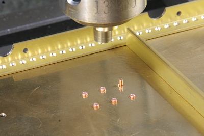
I chose 4 mm dia. rivets for dummy use. The photo shows a rivet set for a flange. In the model, there is no real flange and the rivets are dummy.

Some rivets are utilized to fix brass angles. I chose 5 mm dia. rivets for this purpose.
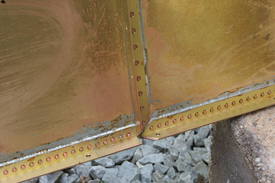
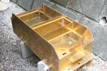
The brass angles are caulked with soft solder. Apply flux, put short solders in line, and heat gently with a gas torch. Care must be taken not to overheat the tank body. Brass sheets are easily warped by heat.
The rivets for dummy use are also caulked with soft solder.
The water tank rim around the top is also fixed by copper rivets. The rivets are put from the inside, pressed and soft soldered on the outside.
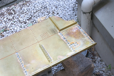
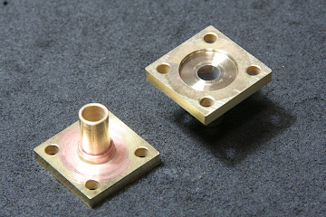
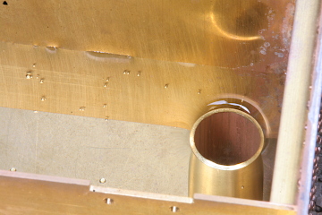
The non-pressure water outlet of the tank is prepared as a small well under the tank bottom.
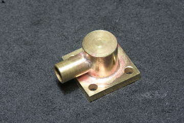
These are wells for the axle-driven pumps' suction lines.
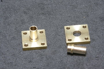
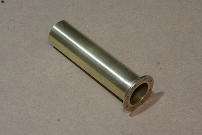
This is an overflow pipe to eject excess water from the tank. It was made with a brass pipe and a flange plate.
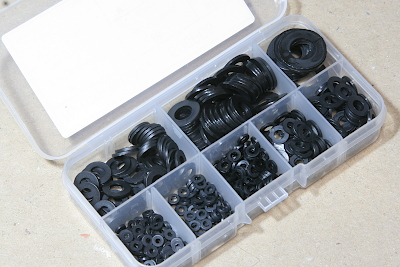
To seal the tank for the leak test, I obtained nylon washers in various sizes.
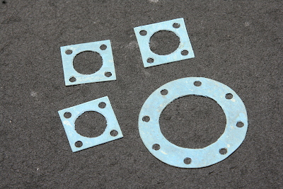
Especially for the overflow pipe and the wells, I prepared gaskets cut from a 0.5 mm gasket sheet.
After sealing the whole tank, the leak test was executed. Unlike the boiler, it was passed on the first try.
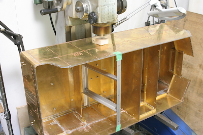
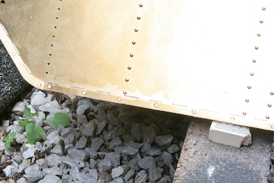
There are some warps in the side plates caused by heating. They were trued up by pressing with the milling machine head.
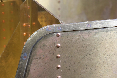
The tank rim is soft soldered. The rim's surface is filed flush, so as to erase the rivet trace. It is the same manner as the full-scale tender.