< Emergency Hand Pump >
The emergency hand pump is mounted laterally on the bottom of the water tank. The operational handle will be inserted and used. Given the large boiler capacity, I designed the hand pump to be relatively large. It features a 20 mm bore and a 36 mm stroke. The following is the process of making its components.
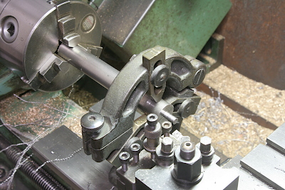
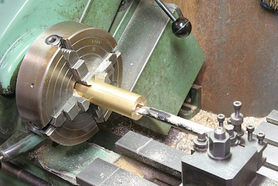
The ram is made from a 20 mm free-cutting stainless steel bar. As the 20 mm bar cannot pass through the lathe's headstock, the bar blank is supported by the fixed steady. Initially, the front step that extends into the valve chest is turned.
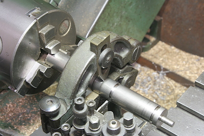
O-rings are incorporated at two positions. While one O-ring is sufficient for sealing, the presence of two O-rings floats the entire length of the ram from the cylinder wall. This minimizes wear on the brass cylinder. The photos illustrate how to turn the grooves for the O-rings. The squeeze compression measures 0.25 mm in the section diameter.
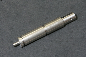
The rear end of the ram is turned to form a step and drilled before cutting a slit for the link. I employed the Keats Vee Block to hold the ram vertically on the stage. The photo on the right shows the completed ram.
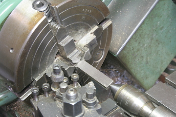
The cylinder is turned from a brass round bar. In the four-jaw chuck, it is drilled through and finished using a boring bar.
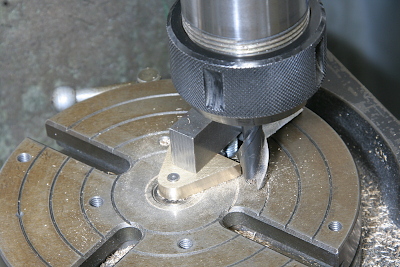
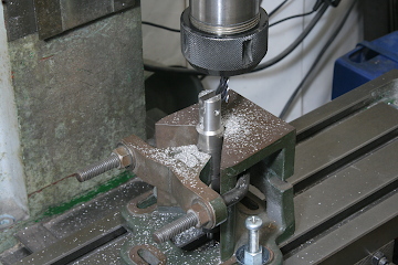
A triangular bracket that will be mounted on the cylinder is crafted from a brass flat bar. The round profile is milled using the rotary table.
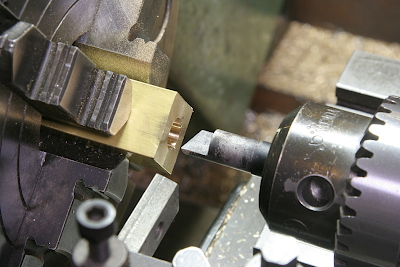
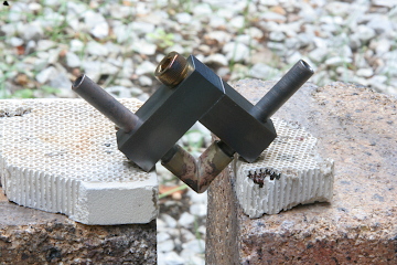
The valve chest is made from a brass square bar. It necessitates upper and lower check valves. The valve seat for the upper valve is directly formed in the chest body. To cut the 75-degree acute angle seat, I fashioned a D-bit shown in the photo. Drill the body partway through and finish with the D-bit.
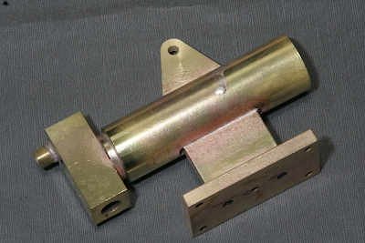
Silver-solder the valve chest, the rectangular bracket, and the pedestal onto the cylinder. This completes the hand pump body.
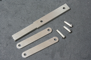
The photo illustrates a lever, two links, and connecting pins, that will be connected to the rear end of the ram. The pin is secured with E-rings. As the upper part of the lever will catch a brass pipe as an extended handle, the side faces of the part are turned round in the lathe.
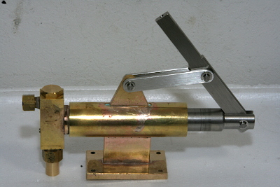
The photo shows the assembled hand pump. The nipple under the valve chest serves as the water inlet, including a brass mesh for filtration.
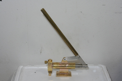
It is the state with the handle installed. The pump body will be submerged in the water tank, while the handle will extend above the top plate.
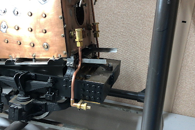
Here I have prepared fittings from the boiler to the tender. The left check valve on the boiler back head is utilized. The following are explanations for each part.
Most of the fittings will be concealed in the cab, except the lower connecting parts. Thus, I fashioned an elbow to represent a real connection at the bottom. The elbow is made from a brass round rod. Two parts that were drilled through and cut at an angle are set in a jig, as shown in the photo, for silver soldering.
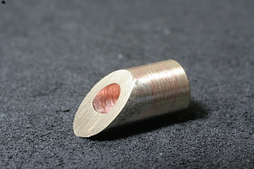
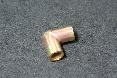
After soldering, the elbow is filed into shape. To prevent remelting of the silver solder, I employed Comsol soft solder for connections between the elbow and pipes.
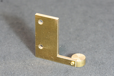
The terminal of the fittings was affixed under the rear frame casting with screws. I prepared a bracket for this purpose.
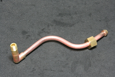
The copper tube is bent and silver-soldered to the connecting parts. The bottom end is connected to a nipple through the elbow, while the upper end has a union connection.
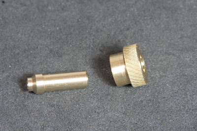
From the tender, a flexible tube will be connected to the nipple. To facilitate finger tightening of the nut, it has a knurled round shape.