< Tender Fittings >
The diagram below illustrates the arrangement of the tender fittings. The high-pressure water line for the engine is formed by merging the outputs of the axle-driven pumps and the hand pump. The axle-driven pump output includes a branch leading to the bypass valve, which regulates the pump's flow rate. At the end of the axle-driven pump output, there is a check valve to prevent backflow from the hand pump to the bypass valve. Additionally, a non-pressure line is separately delivered to the engine, equipped with a stop valve. This non-pressure water is intended for an injector and a donkey pump.
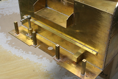
The hand pump is raised from the bottom of the water tank. The rising stage is extended and reinforced by brass angles, to counteract the lever operating force.
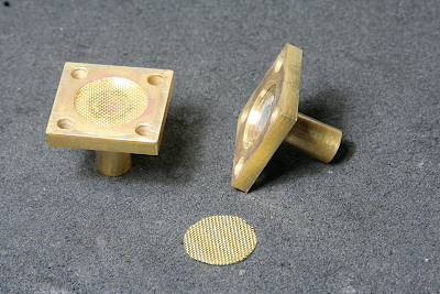
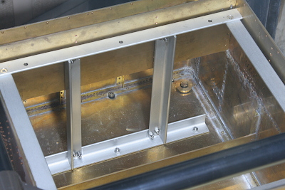
Brass mesh filters cover the suction wells of the axle-driven pumps.
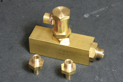
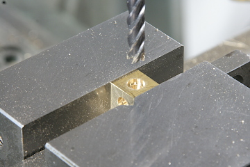
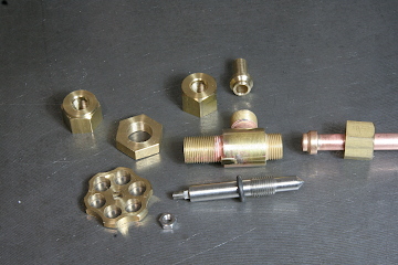
The outputs of the axle-driven pumps, the bypass valve branch, and the check valve converge in a brass block, which will be secured on the tank bottom using nipples screwed into the block through the tank bottom plate.
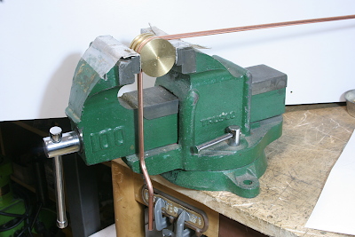
As usual, the copper tubes are bent with a pulley. The tubes remain unannealed.
The outputs of the two pump types merge in a brass cube, with copper tubes silver-soldered to the cube.
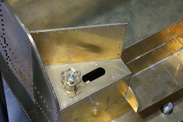
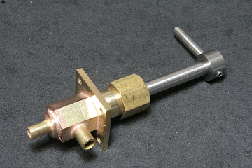
The needle-type bypass valve, similar to the blower valve, is positioned on the right shoulder of the water tank for convenient operation while in motion. A long hole window next to the valve body allows for checking the returning water.
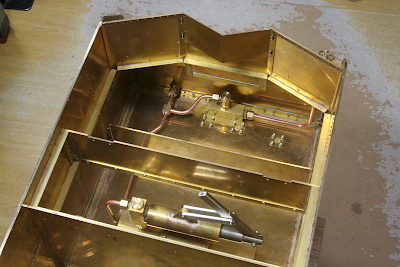
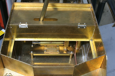
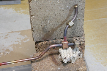
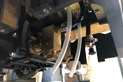
The photo illustrates the tube arrangement of the high-pressure line. The outputs of the two pump types merge on the left front side from the hand pump. All components will be submerged underwater.
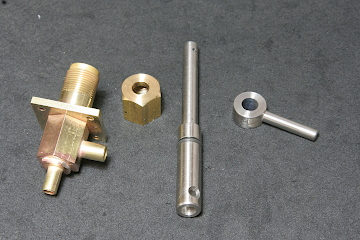
The non-pressure line's stop valve features a spindle valve with a cross hole, requiring only a 90-degree rotation to operate from fully closed to fully open. Note that the spindle has an O-ring to prevent water leakage.
Under the front deck, the left side accommodates the non-pressure line, while the right side is designated for the high-pressure line. The high-pressure line lacks a stop valve but includes an elbow.
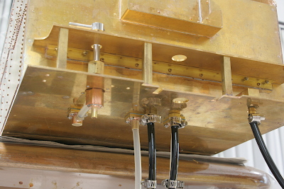
For connections between the axle-driven pumps and the water tank, silicon tubes are used for non-pressure suction lines, while urethane tubes are employed for high-pressure delivery lines due to their pressure resistance and flexibility. Hosebands secure each urethane tube end.
The water tank is mounted on the chassis and secured by 14 M4 screws and two M5 screws, all sealed with nylon washers.
To connect the urethane tubes to the pumps, the first wheelset is removed from the front truck. Afterward, the wheelset is restored, and non-pressure lines are connected.
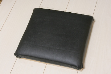
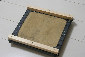
The driver's seat is constructed by mounting urethane mat on a wooden panel, wrapping them with vinyl leather, and securing the leather at the back side of the panel with a tacker.
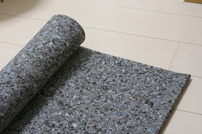
The urethane mat is sold for chair repair purposes. Three mats, each with a thickness of 10 mm, are stacked.
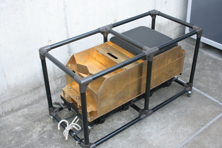
The test run preparation was completed. Detailed components will be manufactured after the test run. A carrying case, utilizing Yazaki's Creform system, was constructed. Note that the driver's steps and the brake pedal are removed for space-saving purposes.