< Main Frames >
Material for the main frames is bright or
black mild steel plate. The former is more
accurate in thickness and easier to scribe
while the latter has smaller stress in the
metal. I chose bright one. To cancel the
warp by the stress after cutting, first I
cut radius and slots in smaller size, after
that I scribed true cutting edge and true
position for holes, and cut them to final
size.
Metal cutting work is completely different
from the wood cutting work. If you are familiar
with the latter, it is worth while changing
your
style as follows.
1) Use a tough gun-grip hacksaw with H.S.S.
blade and cutting oil.
2) Grab both end of the hacksaw and fix your
right elbow to your side (if you are right-handed).
3) Swing your whole body, not your arms.
4) When you move forward, load your weight
to the hacksaw until vapor of cutting oil
rises from the blade.
5) Don't rush! Move as slowly as you can
continue the movement.
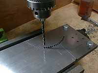
Two plates are bolted together in each end.
The longitudinal edge and the horn slots
are sawn by the hacksaw while curved edge
is broken out along a series of drilled holes.
As I described, in this stage, the profile
of the frame is a little larger than the
final shape.
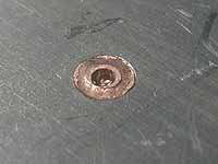
To stand against hard machine work, I also
fixed the middle of the plates with copper
rivets. The rivets are headless not to disturb
the set up for machining.
Over 600mm longitudinal edge in the frame
must be finished exactly straight. The guidebook
said "If you don't have large miller
enough to cut the length, scribe with a rule
and finish with a file." It sounds terrible
for me so I took another method as follows.
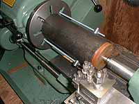
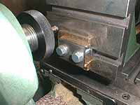
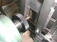
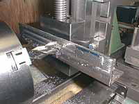
1) Stand the rough cut frame upon the lathe
bed with two blocks under each end of it.
2) Scribe a horizontal line by a height gauge
in the excess area of the plate. (See picture
in the left)
3) Scribe vertical lines in every 100mm distance,
punch and drill small holes - the distance
100mm is about 2/3 of the lathe's cross slide
travel.
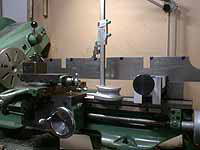
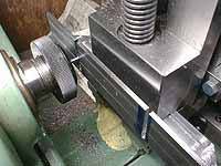
4) Push small pins into the holes.
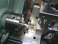
5) Check the straightness of pins on the
lathe bed. (See picture in the middle)
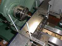
6) Fix a black steel angle (over 100mm) on
the cross table of the lathe.
7) True up the front face of the angle with
a large endmill in the headstock.
8) Lay the frame on the cross table with
two blocks under it - the height of the frame
bottom should be slightly higher than the
angle.
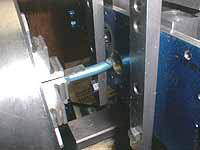
9) Push a pair of pins against the angle
plate and fix the frame using suitable clamps
- now the scribed line on the frame becomes
exactly parallel to the cross slider.
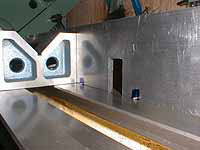
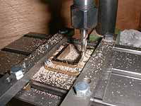
10) Cut the edge with endmill for 100mm length.
(See picture in the right)
11) Loose clamps and slide the frame about
100mm to allow the angle catch the next pair
of pins.
12) Cut the next 100mm edge with the endmill
to the same depth.
13) Repeat this operation and cut whole edge.
14) Check the straightness on the lathe bed
and saw off excess area together with pins.
15) Repeat the same procedure for opposite
side, pushing the finished edge against the
angle.
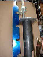
So as to scribe vertical lines on the frame,
three steel cylinders are piled up to raise
the height gauge. Each cylinder was turned
to 200.0mm previously.
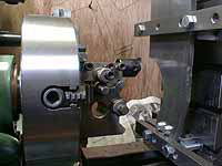
To cut large arcs and holes, a fly cutter
or a boring tool is chucked in the headstock.
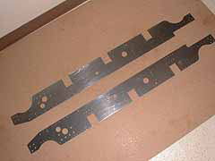
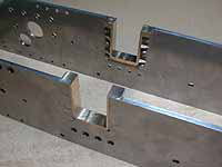
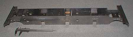
Finished frames.
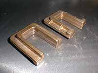
The hornblocks for William aren't castings
but hot pressed brass closed to the final
size. They can be finished with careful filing
but I machined them to ensure accuracy.

A dead copy of the horn slot in the frame,
as a jig to cut the hornblocks.
First the bolting face is milled to final
depth and width to fit to the jig.
In the jig, the backward protrusion was cut
by endmill and filed flush.
Cutting the top face to the final thickness.
In this stage, inside of the slot is not
finished yet.
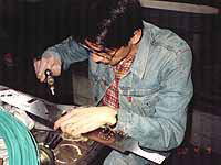
Riveting the hornblocks to the frame. Too
noisy work!
Cutting the horn slot to the final width
with a large endmill.
Buffer beam is made from a black steel angle
- cheap and low quality material. Choose
truer part of the material and true up with
an endmill.
Slots for frames are cut by a small endmill.
The frames are erected with flat and round
stretchers made from bright mild steel. Lathe
bed is suitable to arrange two frames parallel.
We can determine true position of stretchers
on it. After bolting all of the stretchers,
the buffer beams are fixed to the frames
with small angles as follows.
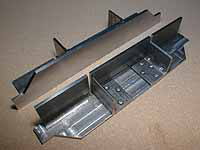
1) On the lathe bed, mount the buffer beams
onto the frames. Ensure parallel arrangement,
using a suitable packing between the buffer
beam and the lathe bed.
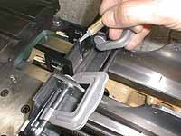
2) Fix the small angles to the corner with
suitable clamps, and drop the quick adhesive
between the buffer beam and the angle. (See
picture in the left)
3) Remove the buffer beams together with the angles
from the frames.
4) Drill through the buffer beam and the
angle, and counter from the front.
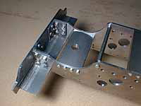
5) Insert iron rivets from back, hammer into
the counter and file flush. (See picture in the
middle)
6) Again, on the lathe bed, fix the buffer
beams onto the frames with clamps.
7) Copy the holes in the frames to the angle
and bolt them together. (See picture in the right)
| TOP | BACK | NEXT |