< Brake Valve 2 >
When making the brake valve handle, I opted to use the lost-wax casting method for the base, as it has a particularly complex shape. I first created a wax pattern by milling both sides using Modela, then sent it off for casting.
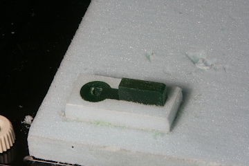
The photo shows the completed lost-wax base. I will drill the required holes and finish the square opening with a fine square file.
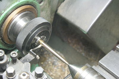
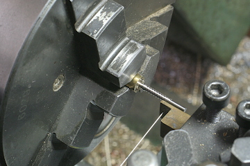
For the handle’s cock section, I shaped a brass round bar into a taper. This was done by chucking the tip side and supporting the base side with the tailstock for stable turning.
The rounded tip of the cock was, as usual, filed to its final form after roughing in steps.
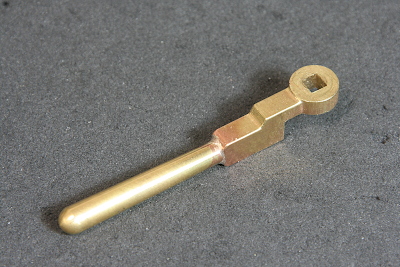
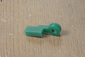
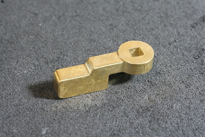
With the lost-wax base and the cock prepared, I silver-soldered them together to complete the handle.
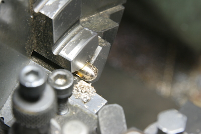
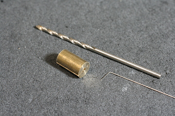
The internal spring that pushes the plunger within the handle is extremely small. I wound a 0.3mm spring wire around the shank of the 1.7mm drill, using a custom brass collet to hold the drill in the three-jaw . This collet also includes a small hole to secure the spring wire, preventing it from spinning during winding.
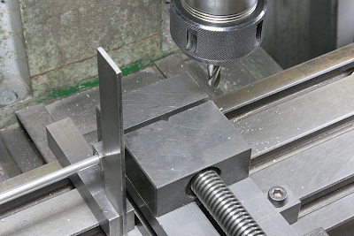
The end of the handle shaft is shaped into a square to match the handle’s square hole. I used a sleeve to index the 90-degree angles and milled it with an end mill. Incidentally, the moving jaw of my vise has a horizontal V-groove, which makes it easy to hold round stock at a consistent height, allowing me to cut all four sides without readjusting the mill height.
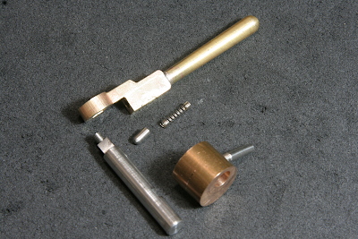
Here’s the full set of parts for the handle assembly. The handle shaft is fitted with a phosphor bronze eccentric cam. This cam is secured by a locking screw against a flat cut in the shaft base. The screw also doubles as a push rod for the release valve.
The brake cylinder is fitted with a drain valve (on the left) and a lubricating valve (on top). The drain valve uses a spring-loaded ball design that opens at pressures below 0.1MPa to release condensation during the early stages of braking. Once the pressure exceeds 0.1MPa, the valve closes, directing steam into the cylinder. The lubricating valve is based on a snifting valve design, allowing oil to enter the cylinder when at atmospheric pressure. It closes during braking, maintaining the oil within the cylinder. Oil is supplied from the sandbox, as with the inner main rod’s lubrication, and is only applied at the start of the daily operation.
The drain valve components are shown here. Like the plunger spring, it uses an ultra-small spring.
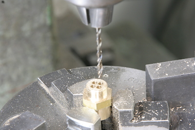
The base of the lubricating valve features four holes arranged around the circumference to allow oil to pass around the ball valve.
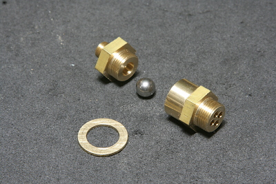
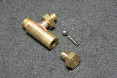
Here are the components for the lubricating valve. To prevent the steel ball from sticking to the valve seat, a larger (and thus heavier) ball was used compared to the drain valve.
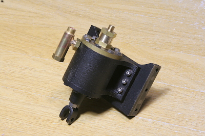
The photo shows the drain and lubricating valves installed on the cylinder. The final step will be to paint all parts black for a consistent finish.
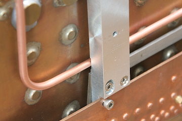
The brake valve piping is mounted along the side of the firebox. I added a cutout to the back of the aluminum support to allow the pipe to pass through.
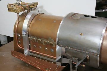

Finally, I removed the brake valve assembly, connected the brake cylinder, and conducted an air pressure test. The pressure increased with the handle’s rotation, the drain valve closed at around 0.1MPa, and the pressure continued to rise linearly up to the full boiler pressure. With steam, there will be condensation, so it may not operate as smoothly as this, but it should still be practically acceptable.
Video clip of the brake valve test --->