< Modifications >
This month, I’d like to report on a series of modifications, prompted by issues found during the previous test run as well as some design improvements.
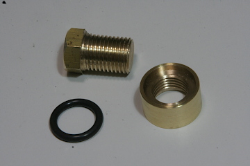
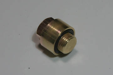
During the test run, I discovered a water leak from the water gauge drain cock. As a countermeasure, I added an O-ring and a nylon washer to improve sealing. Here are the details.
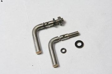
A groove was cut into the base of the drain cock’s tapered spindle to accommodate an O-ring. For this, I used a 0.6 mm parting tool ground from a general-purpose lathe bit. To hold the tapered shaft securely in the three-jaw chuck, I fabricated a custom brass collet. On the tip side, sealing was achieved using a nylon washer. The photo shows both individual parts and the assembled unit before installation into the main drain valve body.
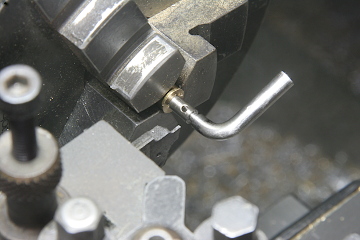
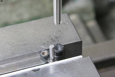
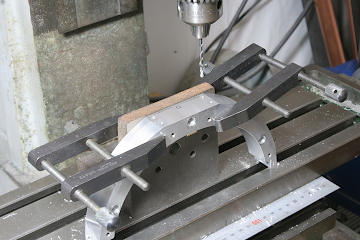
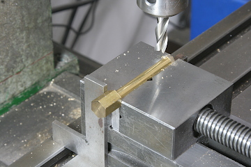
Initially, the operating lever for the cylinder drain valve was built to scale, but it proved too weak during use. I decided to enlarge the operating arms and increase the shaft diameter from 4 mm to 5 mm. The latter required enlarging the bearing holes, as shown in the photo where I’m using a hand reamer after drilling through. The hand reamer has to be turned by hand.
The newly enlarged operating arms were cut via laser machining. On the left-hand side of the locomotive, the original design had separate upper and lower arms. In the new version, these are integrated into a single solid piece. After annealing the material, I bent it to the required angle using two bench vises - clamping the straight section and leaving the bend free.
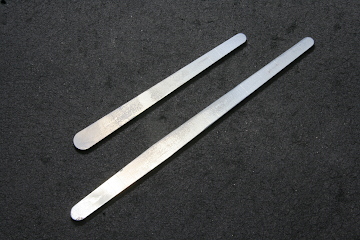
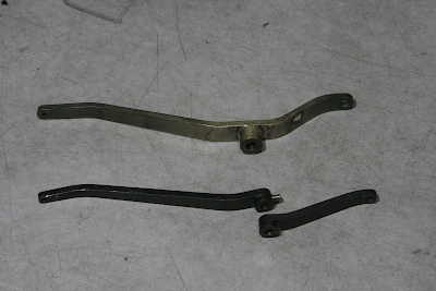
A steel bushing was then silver-soldered into the bent arm. The photo shows the new left-hand arm (top) compared to the previous version (bottom).
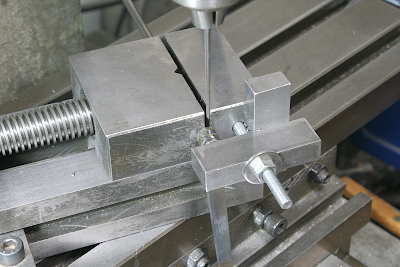
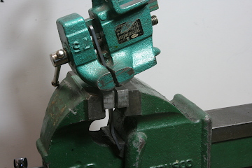
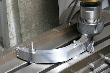
To securely fasten the arm to the shaft, I opted for a taper pin rather than a setscrew, which tended to slip. Using a taper pin reamer, I machined both the arm and shaft simultaneously while holding them rigidly in the vise. The photo shows the right-hand arm during this process. To avoid interference with the stage, the vise was set at an angle.
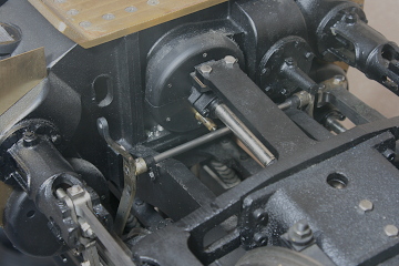
Here’s the final assembly with both arms mounted. The upper left arm is operated via a reach rod from the cab, while the downward-pointing arm is linked across the locomotive, allowing synchronized movement. Though the levers are currently quite noticeable, they will be painted black to blend in with the frame.
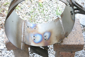
Previously, the steam turret could not be installed or removed with the boiler cleading in place, which made maintenance difficult. To resolve this, I modified the upper rear section of the boiler cleading to allow access with the turret installed. First, I milled off the top of the aluminum U-shape frame inside the boiler cleading. This area will eventually support a lubricator for the donkey pump, so I also tapped holes for mounting it.
With the U-frame installed and the modified cleading in place, the steam turret can now be threaded in without interference, as shown in the photo.
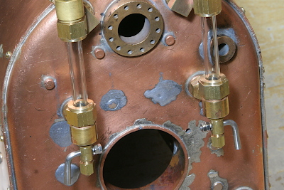
During the test run, I filled the boiler by removing the safety valve. To improve this, I decided to add a dedicated water inlet on the top of the steam turret. I drilled and tapped a hole for a threaded plug, identical in structure to that used on the Hunslet locomotive.
The plug is sealed with O-ring between top and bottom. For O-ring retention, I fabricated an outer ring as a separate part and silver-soldered it in place for a secure seal.
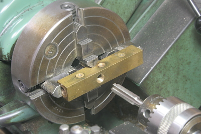
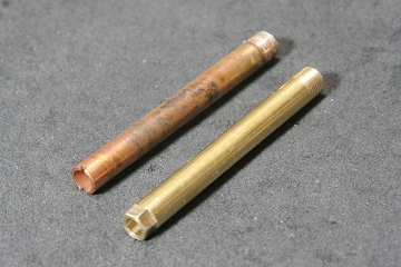
The original piping between the regulator body inside the steam dome and the superheater tubes was made from threaded copper tubing. However, the threads were becoming worn, so I machined a new pipe from solid brass stock. The new part is shown at the bottom of the photo. Unlike the previous version which had a slotted head for a screwdriver, this one features a hex head so it can be tightened with a wrench. To machine the hex, I fixed a hex bar to the opposite end of the shaft and indexed the part with a square to cut each facet precisely.
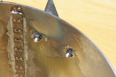
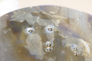
The brackets on the boiler cleadings are fastened with M3 screws and nuts. To simplify removal, I soldered the nuts directly to the inner surface of the boiler cleadings, allowing the brackets to be removed from the outside using just a screwdriver.
To position the nuts accurately, I mounted the brackets and flowed solder only into the nuts. I used aluminum screws to hold everything in place during soldering, since solder doesn’t adhere to aluminum. The nuts had their black chromate coating stripped off before soldering.
Because the boiler casing gets very hot from the boiler beneath, I used high-temperature soft solder. The heat burned off the black finish, exposing the bare steel underneath.