< Parts Around Smokebox >
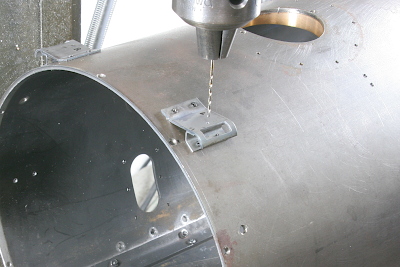
To attach various detail parts to the smokebox, I began by opening additional holes. The smokebox shell is 2.3 mm thick, allowing me to tap the holes and secure the parts with screws.
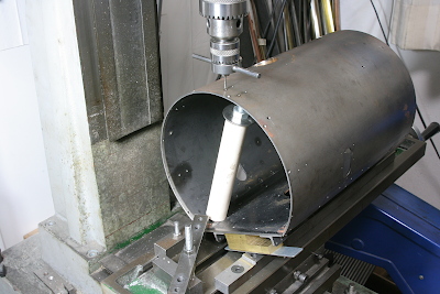
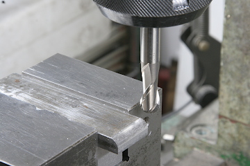
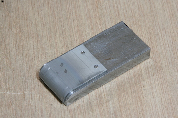
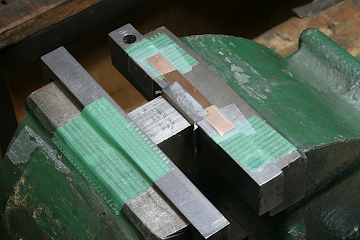
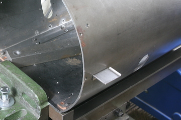
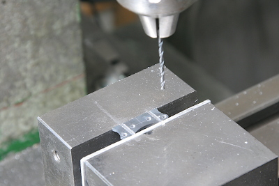
Next, I fabricated the upper steps that mount to both shoulders of the smokebox. For the top plates, which feature rounded ends, I first prepared a former from a flat bar using ball end mill. I then cut 1.2 mm steel sheets, annealed them, and shaped them using the former. To prevent slippage during the shaping process, I inserted pins through the fixture holes.
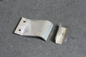
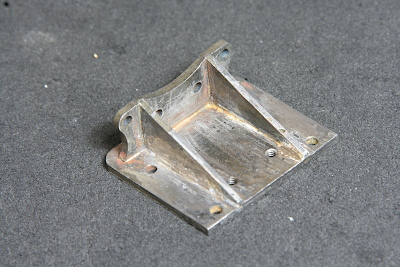
The support brackets beneath the top plates were shaped into an obtuse U-form using another former. On the right, you can see the completed top plates and the support brackets.
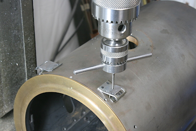
Both parts were temporarily mounted to the smokebox to fine-tune the fit, ensuring tight contact at the joints.
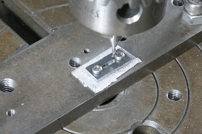
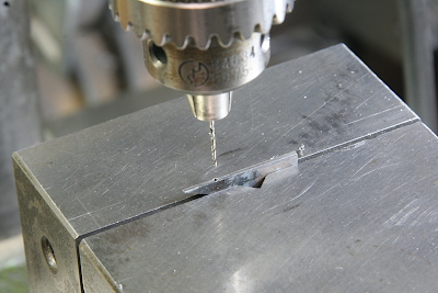
At this stage, I opened up rectangular windows in the top plates and drilled holes for fasteners. I had intentionally left the windows unopened earlier to avoid any distortion around the openings during shaping.
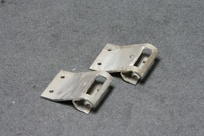
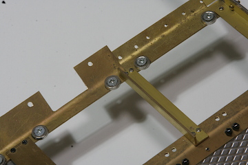
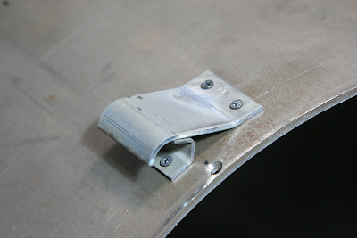
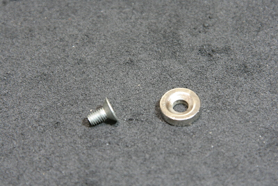
With all shaping complete, I assembled the upper plates and brackets and silver-soldered them together. After soldering, I ground off the heads of the mounting screws. In the photo, the background shows the unground screws, while the foreground shows the finished result.
The parts were then reattached to the smokebox. Finally, I drilled and tapped the holes needed to attach the deflector supports, completing this assembly.
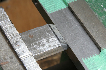
On both sides of the smokebox, simple sheet-metal lower steps were added. These are single bent plates. When forming the bends, a slightly obtuse angle was required, so I used a vise lined with brass strips to fine-tune the bending angle.
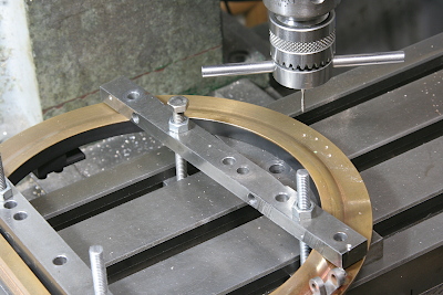
For the lantern stands mounted to the pilot deck, I machined a long slot into the base part to insert the support post.
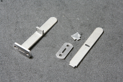
Here you can see the individual components before assembly, and how they look once silver-soldered and completed.
To mount the headlight bracket to the smokebox front plate, I drilled and tapped the front plate.
This photo shows the vertical plate of the headlight bracket being processed—with holes drilled and slots machined to hold the horizontal beam.
I also drilled tiny holes into the cross-sections of each component to insert alignment pins. This included drilling 0.6 mm holes into parts only 1.2 mm thick.
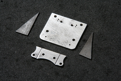
Here are the finished parts. I used 0.6 mm brass wire as pins for alignment during assembly.
Once all parts were assembled, I silver-soldered them. The tips of the pins were then filed down. The photo shows upside down view after completion.
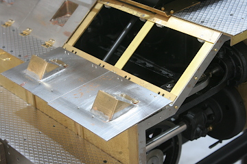
To prevent the valve gear covers on the pilot deck from flapping due to vibrations while running, I decided to hold them down with magnets. In fact, I specifically made the covers from steel instead of brass for this reason. I used 9.5 mm diameter neodymium magnets with mounting holes.
I drilled and tapped the brass beams beneath the covers to mount the magnets—two per cover. The magnets are separated from the cover by the 1.2 mm thickness of the brass beam, which would normally weaken the magnetic attraction. However, by switching the fasteners from brass to iron screws (which become magnetized), I was able to achieve a strong holding force.