< Reverser Fittings and Others >
The C53 is equipped with a power reverser. While the full-size locomotive uses air power, in this live steam model it will be steam-driven. As with the steam brake, it is essential to deliver steam to the reverser cylinder without cooling it along the way. On the prototype, the power reverser is mounted toward the front of the boiler on the left side. To keep steam exposure to a minimum, I decided to take steam directly from the steam dome, route it through the boiler’s front extension (part of the smokebox), and connect it to the reverser with minimal outside piping.
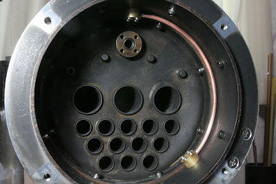
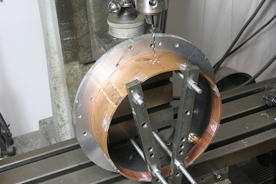
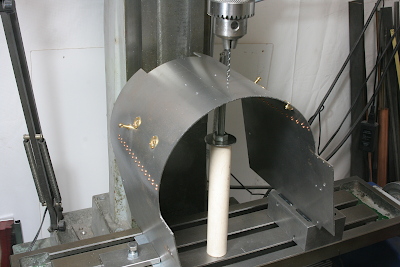
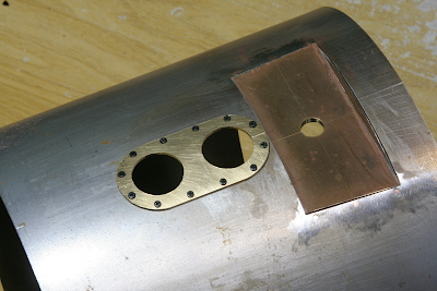
The photo shows the boiler viewed from the front. Forward of the smokebox tube plate is the extension section, which forms part of the smokebox. Steam enters the smokebox from above, is led along the wall in copper tubing, and emerges immediately beside the power reverser.
From the steam dome to the extension section, the connection runs along the outside of the boiler—still within the boiler cleading and fully lagged for insulation. Inside and outside of the smokebox are joined using two brass columns clamped together.
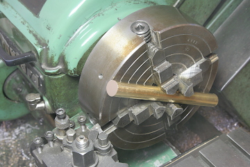
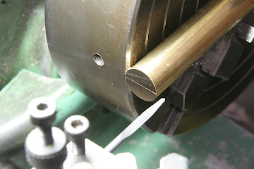
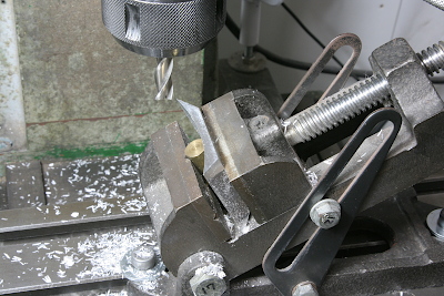
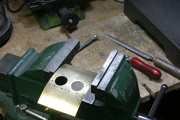
The mating surfaces of these brass columns require convex and concave radii—concave for the outside column (similar to the generator mount described later) and convex for the inside column. For the convex cut, I chucked a brass round bar in a four-jaw chuck and machined the end, then scribed the centerline using a scribing needle mounted in the toolholder.
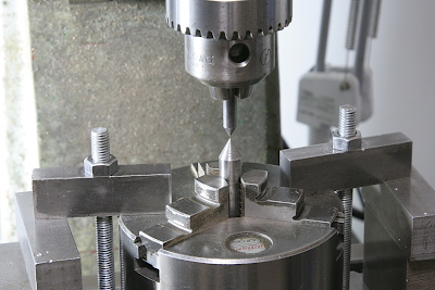
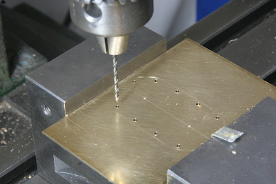
Mounting holes for the columns were drilled using coordinate positioning with a three-jaw chuck fixed to the milling stage. To set the origin, I first chucked a center in the three-jaw, brought it into contact with the spindle center, and aligned them.
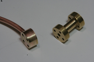
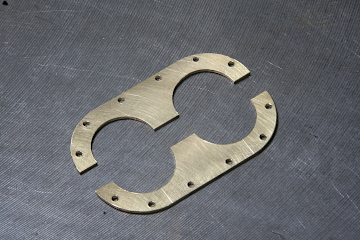
The central hole serves as the steam passage, while the four surrounding holes are for mounting bolts. Since the surface is curved, I milled a flat spot before drilling. The inner column has through-holes; the outer column has blind holes tapped for screws. Tape was applied among the jaws to prevent the work from dropping when freed.
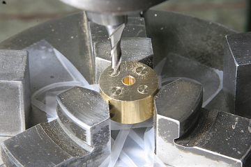
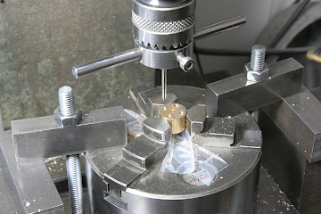
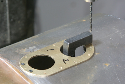
With the columns paired, I drilled the holes for the copper pipe connection—first creating a shallow recess with an end mill, then drilling through with a thinner drill to create a stepped hole.
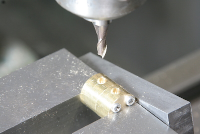
Next, I removed the boiler extension section and drilled the mounting holes for the columns, again with a central steam passage and four bolt holes around it.
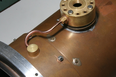
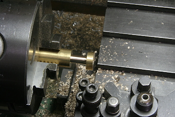
On the outlet side, an H-pipe was machined with a parting tool to bring the steam out through the boiler casing and connect it to the power reverser.
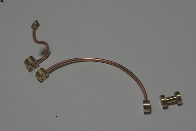
With the copper tubing silver-soldered, all the parts were complete. For final installation, I will apply high-temperature sealant to all mating surfaces.
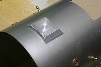
The generator mount at the rear of the boiler cleading is fabricated from aluminum alloy block rather than the prototype’s sheet-metal construction.
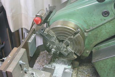
First, I machined the curved surface to match the boiler cleading using a fly cutter mounted in the lathe. The tool bit was held in a four-jaw chuck as usual. The red button on the setup is an emergency stop switch, which automatically stops the lathe at the end of the powered feed stroke.
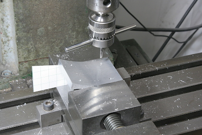
I then tapped the mounting holes perpendicular to the curved surface, using a paper angle gauge for alignment. After that, on the front face, I drilled the threaded holes for securing the generator itself.
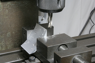
The angled shoulders were cut using side milling.
The angled front and rear faces were cut. Set up in an angle vise for face milling. This completed the main body machining.
Finally, I drilled the mounting holes in the boiler cleading, adjusting the height of the lower edges so the holes would be perpendicular to the curvature. The generator mount is secured from the inside of the cleading with screws.
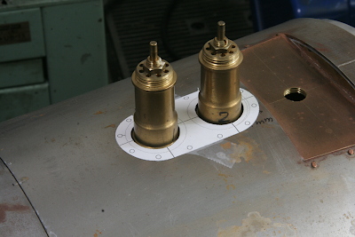
The safety valve threads directly into the boiler through a hole in the cleading, with the gap around it closed by a safety valve cover. Since the safety valve’s position is set by trial fit, I first made a paper template to check the mounting position. The photo shows the valves with their top caps removed.
Using 1.2 mm brass sheet, I scribed the cover’s shape and drilled the mounting holes first.
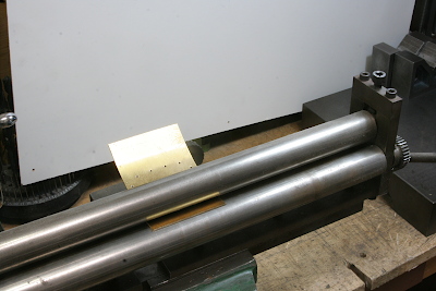
The sheet was then rolled to match the boiler cleading’s radius.
The shape was cut out with a fretsaw. The cover is made in two halves so it can be removed without dismantling the valves itself.
With the rear holes drilled, tapped and the cover temporarily fixed, I transferred the positions for the remaining holes, countersinking them for M2 screws. After removing the cover, I drilled through with a 1.6 mm drill and tapped the holes.
Once screwed into place, the cover was complete. The cover must be removed each time the safety valves are removed.