< Cab Floor Assembly>
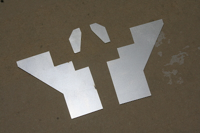
Among the cab floor components, only the rear plate and ribs were prepared using laser cutting. The rest are mostly rectangular parts.
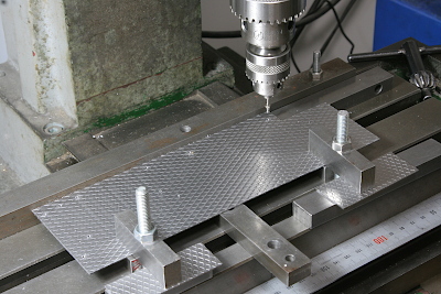
For the floorboards, I used the mesh plate, the same material I used for the running boards. The photo shows the process of drilling screw holes to secure the valances.
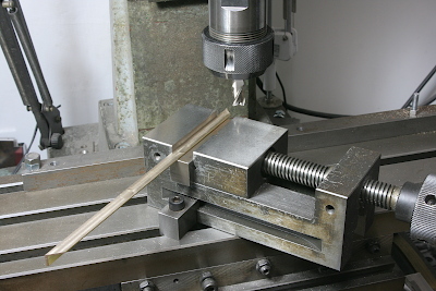
The valances surround the edges of the floorboards. Since they are made of brass angle, I milled the ends diagonally to hide the cross sections, by setting the vise at a 45-degree angle.
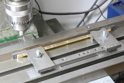
The holes matching those on the floorboards were drilled precisely using milling machine coordinates, without relying on transfer marking.
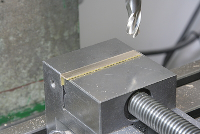
The brass angles varied slightly in squareness depending on the batch; the material I received this time was noticeably obtuse. I corrected this by face milling to restore a perfect right angle.
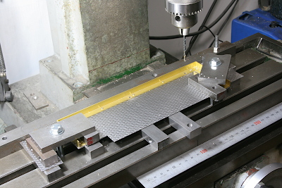
After attaching the brass angles (which form the valances) to the floorboard, I drilled the mounting holes for attaching the cab.
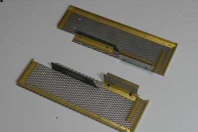
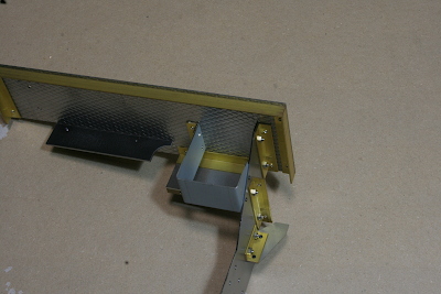
Here is the completed floorboard viewed from below. The inner vertical plates are a dummy representing the rear end of the boiler cleading and also a vertical plate to conceal the step between the floor levels. Brass angles for attaching the rear plate are also installed.
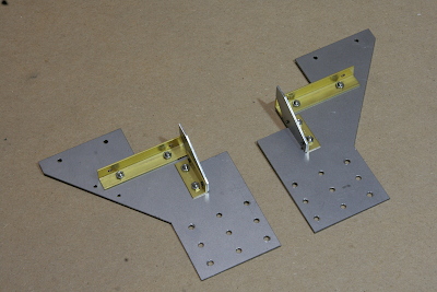
The laser-cut ribs were attached to the rear plate using brass angles, just as the full-size locomotive uses steel angles of nearly the same dimensions. Holes were drilled at the lower edge for mounting to the rear buffer beam.
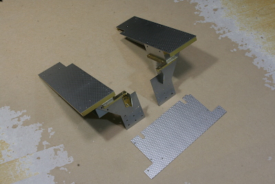
The left and right floorboard assemblies were then completed separately. These will be mounted on each side of the boiler and connected by the central floor section made of the mesh plate.
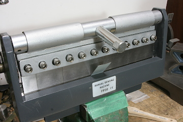
On the left side of the cab, I added a shelf to support the air distributor. The shelf was made from sheet steel bent into a U-shape using a bending brake.
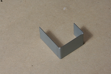
This shelf spans between the left floorboard and the rear plate.
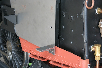
The front edges of the floorboards are supported by angle brackets attached to the boiler cleading, made from machined steel angle stock. To ensure the floorboards are symmetrical and parallel to the running boards, I used an angle gauge while setting their position.
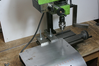
The photo shows the process of drilling the fixing holes for the angle brackets in the boiler cleading. Because the opposite side of the U-section would interfere with the machining, I set a small milling machine on the workbench and let the other side of the U-section hang below the table for clearance.
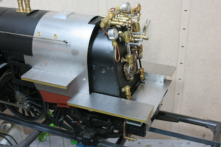
Finally, the completed floor assembly was mounted to the chassis. Note the central floorboard sits one step lower than the left and right sections.