< Cab 1 >
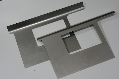
The cab side sheets were laser-cut from 1.6 mm steel plate. Because the joint where they meet the roof requires bending, that work was also outsourced as part of the same process.

The side sheets were attached to the floor using brass angle stock. A cardboard template was made for the cab front sheet, and the gap between the front sheet and the boiler cleadings was checked. In the end, it turned out that the template matched the design almost perfectly, with no noticeable excess or shortage of material.
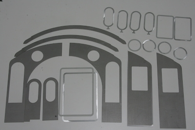
Once the shape of the front sheet was confirmed, the remaining cab parts were prepared with laser cutting. They are the front and rear sheets, the front door, and the roof valance, all in 1.6 mm thickness, while the various window frames were made from 0.8 mm material. Due to material availability, the window frames were cut from bonderized steel sheet.
With the cab front sheet finalized, the running boards were brought to its full length, and holes were drilled at the rear end to connect it to the front sheet.
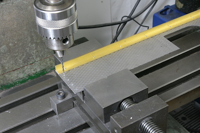
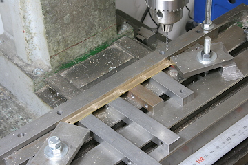
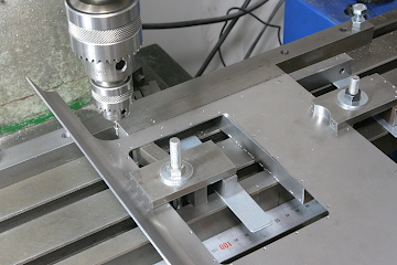
The window frames were temporarily fastened from the inside with M1.7 screws. The photo shows the pilot holes being drilled for tapping in the side window frame. The same operation was carried out on the rear window frames.
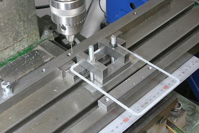
The window frames were clamped to the side sheets and rear sheets, and the holes were transferred and drilled. The photo shows the rear window frame temporarily fixed in place, with pins inserted through the drilled holes to hold the alignment.
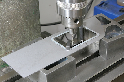
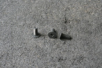
Since windows will be installed, there must be no protrusions on the inside of the window openings in the side sheets. Special low-profile head screws were used, with the heads sunk flush into the inside surface of the side sheets. The counterbores were cut using an end mill.

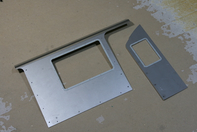
This shows the window frames mounted on the side sheets and the rear sheet. In the final stage, solder will be flowed in and the screw tips filed off to eliminate any visible traces.
Brass angle stock is also used for assembling the cab itself. Round holes are drilled in the angle, while tapped holes are made in the cab walls. The parts are fastened from the inside with screws, and the screw tips are then filed away to remove any evidence of fastening.
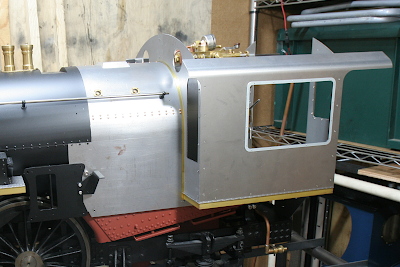
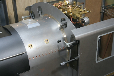
At this stage, the cab is assembled and mounted on the main body to check all dimensions. The gap between the cab front sheet and the boiler cleadings is temporarily packed with a brass strip (boiler band material). For ease of assembly and machining, the front sheet is made in left and right halves, joined at the center by a backing plate fitted from the inside.
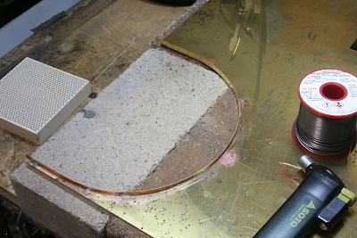
The joint between the boiler cleadings and the cab is an angle structure, built up from 0.5 mm brass sheet. First, a flat plate is cut with U-shaped slots, and the boiler band material is attached. High-temperature soft solder was used to prevent deterioration caused by heat from the boiler.
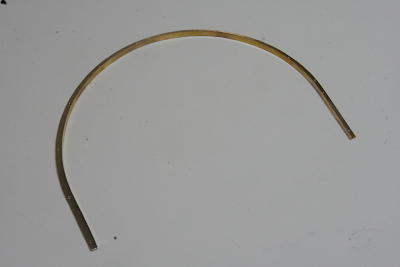
When the flange portions are cut out, the result is a U-shaped angle. The mounting holes are drilled before cutting out the final shape.
The part is positioned together with the cab and clamped to the cab front sheet. After this, it is disassembled and the fixing holes are transferred and drilled.
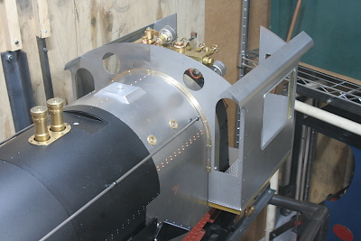
The fully assembled condition. Only the cab side is fixed, allowing for slight movement due to thermal expansion of the boiler.
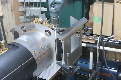
Finally, the rear ends of the running boards are fastened to the cab front sheet. To transfer-drill the holes, the drill bit was extended using a round rod to reach the required position.